Continuing on the quest to make unusual controllers for rhythm games like StepMania, the goal of this project was to make a keypad that would be optimized for fast key presses and nice tactile feedback. I thought for a while about possible button-based approaches, however for maximum agility and repetition the mass of the buttons and the unclear point of electrical contact versus physical distance made it difficult to find a solution that would improve much on just using a regular keyboard. Instead, I decided to try an electrical contact based approach, with a flat metal surface used as the area to press or tap, and the measurement of contact based on direct conductivity (or resistance to ground).
The way this device measures whether a finger is touching the pad is by sending a small (on the order of nA) direct current through the finger to ground, which is amplified by an operational amplifier into a digital signal processed by the Teensy LC. This is different from the increasingly widespread capacitance based measurement for touch sensors - the reasoning here is that resistance measurement will generally be faster, clearer, and more robust to perturbations. Measuring tiny changes in capacitance requires precise timing of charging and discharging cycles, and this whole process takes time. Additionally, the capacitance method imposes limitations on the touch surface area (size and proximity to ground) and wiring. Touchscreen technology has advanced to the point that the capacitance method is used very effectively in "smart" devices, however it is still doubtful whether this is the best approach for fast timing like in rhythm games. In fact, the Teensy LC has built-in functionality to measure capacitance on most of its input pins, precisely for touch sensing, and if you are interested in making a similar controller, using that functionality can greatly simplify the project (as there will be no other components or circuits to build). Capacitive sensing is also nice because you can use an insulating surface over top of the touch pad which also acts as a protective layer against dirt and corrosion. However for this project, I decided on the resistance method, since it is much more robust - when the finger touches the metal surface, there is a resistance of a few hundred kOhm to ground, and then a tiny current is established which can be measured by an op-amp. When the finger is not touching the metal surface, there is a much higher resistance of some 10^15 Ohms, no current, and a zero output to the Teensy. Since there are no high frequency signals involved in the resistance measurement, and no requirements on capacitance or inductance, the metal areas for the touch zones can be arbitrarely shaped and quite large, and the wires to connect the surfaces can be long and unshielded.
In fact, the currents involved are small enough that noise can be a problem. The major source of noise is from coupling to the 60 Hz AC grid. (This noise will also affect capacitance measurements) This is handled in this project in two ways: first, there is a software latch that makes a minimum press time equal to slightly longer than a single AC cycle (17 ms), that way the 60 Hz signal will not pass as an input to the computer in any case. Second, there is a large aluminum block placed strategically under the touchpad area. This block both provides a ground reference for the current in those situations that current can flow continuously, and acts as a source of electrons referenced to ground (a sort of floating capacitor) when the current cannot flow continuously which reduces the voltage fluctuations at the op-amp terminals. I was actually surprised by how much the aluminum block reduced susceptibility to noise. While I get the best touch response performance if I am grounded by touching the aluminum block, and my hands would naturally touch it when using the pad so this doesn't require much forethought (this being the purpose of the plate), I can get almost similar performance even if I am ungrounded, because there is enough current flowing through my finger just due to the 60 Hz AC coupling into my body from elsewhere, and it is in this case that the extra capacitance of the aluminum block stabilizes the signal enough to where the software can filter out the rest of the periodic variation.
The Teensy LC is the main controller, and the algorithm here is very simple. The Teensy measures five digital inputs, and if one is high, it sends out a command over USB to the computer (these represent the four arrows and a central pad). When a release is detected, a 1/60 second timer commences, before the release signal is sent to the computer. This way if the input goes high again within the span of an AC cycle, the button is considered to be held continuously, and spurious noise is rejected. The Teensyduino package makes the PC interfacing very easy - simply install and set the board mode to Joystick+Keyboard+Mouse+Serial, and the Joystick.Button command to programmatically press and release buttons becomes automatically available. No need to worry about USB packets and drivers. Overall I've had great success with PJRC Teensy boards and this project kept the trend. The Teensy LC is a 3.3V board, while the op-amps run at 5V, so each op-amp has a resistive voltage divider to scale its output to 3.3V; the 5V is the primary power source drawn directly from the USB connection.
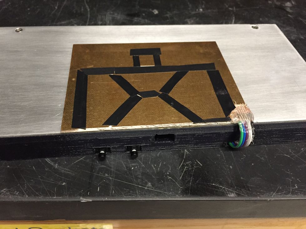
The prototype was completed in a rapid manner by using a rotary tool with a cutoff wheel to etch lines into a single-sided copper circuit board from the scrap pile, and these lines separated the different areas of each touch button. Then wires were soldered on, and electrical tape was used for additional insulation and tactile feedback at the edges of the buttons. These were then connected to op-amps on a solderless breadboard.
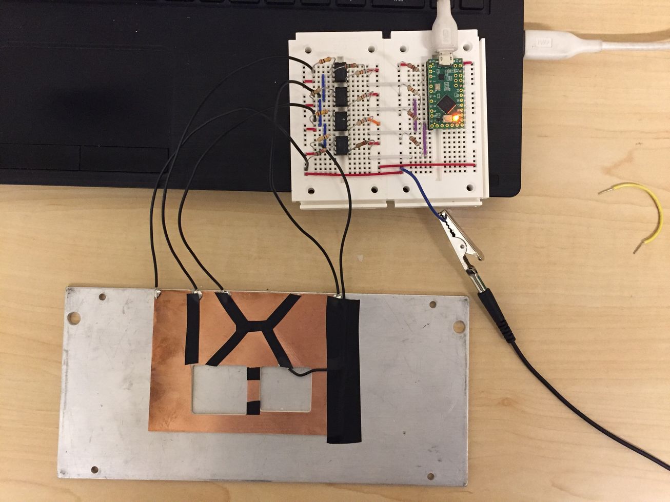
The prototype version of the touchpad controller.
Based on the performance of the prototype, I decided to add three features to the final version. First, I added a central pad below the arrows, as it is useful to be able to advance between songs without taking my hands off the controller. Second, I added two pushbuttons for volume control, to adjust volume without having to switch out of the game. The Teensy Keyboard class makes this type of functionality very easy to implement. Third, I added a headphone jack which would give auditory feedback on when the arrows are pressed, so I can practice keeping a more stable rhythm. Since the headphones are then driven directly by the Teensy, this gives a sub-ms delay between touch detection and audio signal, which would not be achievable if I tried to do this via software on the computer. The schematic for the final version is shown in the images below, and can also be downloaded as a PDF file here.
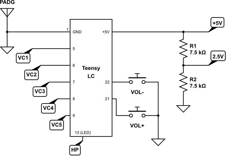
Circuit connections to the Teensy LC include the 5 op-amps (digital input), 2 volume control buttons (digital input with internal pull-up), and 1 headphone signal (digital output). A 2.5V comparator rail is made by dividing the 5V from the USB connection.
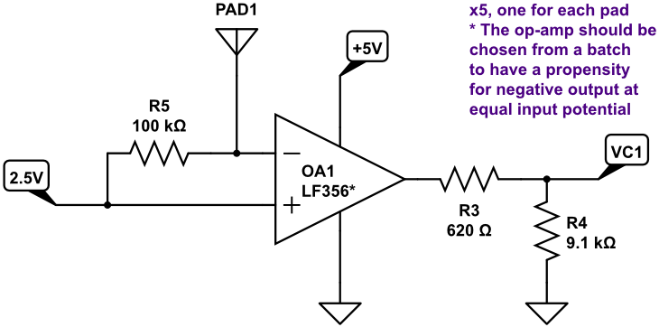
There are 5 op-amps, each connected to a touch pad (PAD1 here), and wired alike. Resistor R5 sets the sensitivity of the op-amp; higher values mean a lower current from the touch sensor will be sufficient to generate a high output. Resistors R3 and R4 ensure the output VC1 to the Teensy will not exceed 3.3V (these could be eliminated if a rail-to-rail op-amp powered off 3.3V is used instead of the LF356).

The headphone jack is connected with this fully isolated arrangement to allow simple pulse generation. Whenever the digital signal HP transitions to 0V or 3.3V, an impulse sound can be heard through the headphones.
With this simple circuit, I designed the layout to use a single-sided PCB, which I could then mill using a CNC router. I used DipTrace for the PCB design, and FlatCAM to generate the g code. On the CNC, I used a feed rate of 120 mm/min at 0.05 mm depth, with 7000 RPM (machine maximum), and a 20 degree 0.2 mm V cutter. For drilling, I use a plunge rate of 17.5 mm/min at 7000 RPM, with drill diameters of 0.8 to 1.0 mm. More details on these parameters here.
On the first attempt at making the PCB, the milling itself went ok (with basic faults from table leveling), but soldering the components was a huge pain. The molten solder would simply bead up and not stick to the board. This was also my experience with the radio acceleration controller earlier where I made the PCBs in a similar manner. I bought a water-soluble flux pen, and with flux applied, the solder would now wet the board, though because there is no masking, the solder would tend to make blobs on the board and short out all the connections. It took a while to get the solder to stay in the correct location, and was very annoying to do. Then, to clean up the flux, I decided to run the board under some water. I used tap water, which had all sorts of minerals and ions in it. This resulted in the copper turning into a green oxide and depositing all over the board, including in the gaps between traces. This was a bit unsightly, but a major difficulty was that the green oxide was slightly conductive (10k to 100k ohms resistance between traces). Considering that the purpose of the board is to measure tiny changes in conductivity, having conduction between the existing circuit traces was not acceptable. After this huge waste of time I just threw out the whole board.
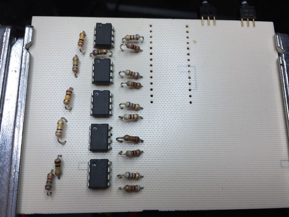
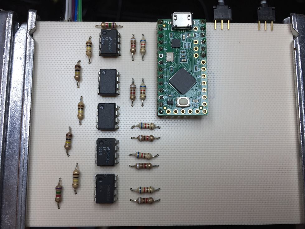
Top of the sensing board with op-amps and resistors installed.

Bottom of the sensing board after a sad and failed attempt at soldering and cleaning off flux.
On the second attempt I tried to really figure out where the soldering problem was coming from. I milled a new board, with a slight modification of properly sized resistor holes and wider isolation zones, and then did a preparation process before placing any components. This involved applying the water-soluble flux, then touching each solderable pad with the soldering iron tip until each pad was covered by a thin shiny layer of solder. This was quite easy to do because the flux makes the copper surface wettable. After that, I rinsed the board using de-ionized water and rapidly dried with a paper towel. This resulted in a clean board with a thin layer of solder already present at the locations where components would need to be soldered in. In fact this sort of preparation of the pads is done by PCB manufacturers before they send out a board (in a batch process of course), which is why I had never realized that I would need to do it with these milled boards. Doing this preparation is a must if you want to use custom machined boards without massive frustration. Once the copper pads are already wetted with solder and flux cleaned off, the components can be placed and soldered very easily. This led to the much cleaner board shown below.
Top of the sensing board with op-amps and resistors installed.
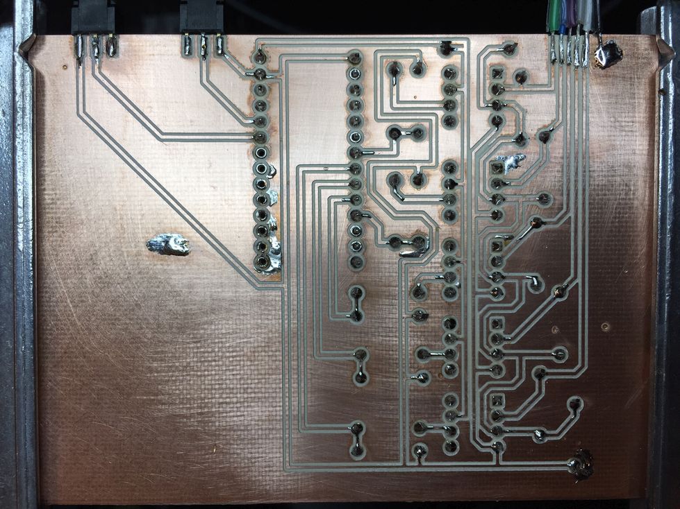
Bottom of the sensing board after successful solder wetting.
For the touch surface itself, from the prototype version I found that the copper formed an oxide layer due to interactions with the oils from the skin (as expected; this can be seen on statues for example). So in the final version, I plasma-cleaned the copper layer and coated it with about 50 nm gold. The gold should provide an oxidation-resistant surface and enhance the measurement of conductivity over a long use time. After gold coating, I milled the pad connections similarly on the CNC, treated the solderable pad areas with flux as above, and then soldered wire connections from the touch pad board to the sensing board. Below the touch board I installed the aluminum plate acting as electrical ground (connected to sensing board ground using one of the screws, since aluminum is difficult to solder), and the sensing board was installed under the plate in a 3D printed case. One could probably make a more clever design where these boards are combined into one double-sided board and then the device could be made very thin without needing the aluminum plate or thick plastic case. Presently the thickness is 0.75 inches which is slightly uncomfortable to use without placing some support padding behind it for the palms.
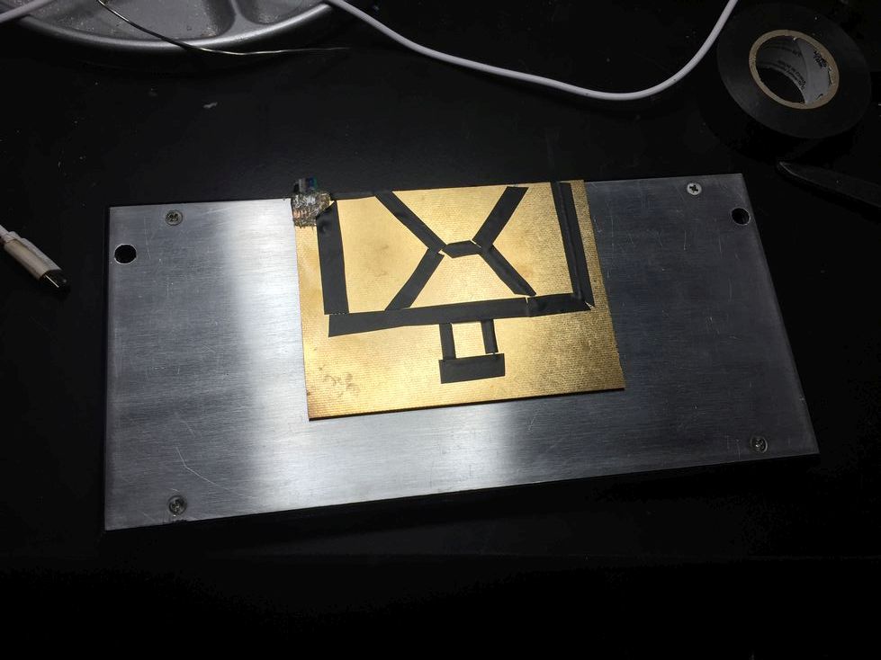
Finished controller, top view. Electrical tape is used to insulate the areas between the touch pads, both to avoid accidentally activating adjacent areas with one touch, and to provide tactile feedback of the area boundaries due to the thickness of the tape. Ideally this sort of thing could be done with a vinyl cutter so it doesn't look this messy.
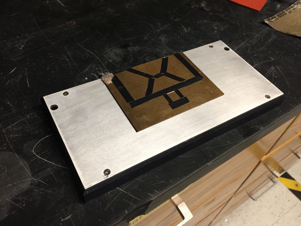
Finished controller, iso view.
Finished controller, back view. The two volume buttons, a hole for the USB plug, and wires connecting the touch pad to the sensing board inside the 3D printed case are visible.
The software side is quite simple as described above. We sense the six digital inputs and then send press or release commands to the computer accordingly, with a basic noise blocking counter. Whenever a touch is detected, pin 13 is toggled, which affects both the onboard LED for visual indication, and the headphone jack for auditory feedback. Pin 23 is optionally toggled at each cycle, which is used with an oscilloscope to establish the timing of the loop and convert the noise blocking counter value from time in ms to number of loop iterations. The code, for Teensyduino, can be downloaded here.
This controller works well! I am quite pleased with the performance, touching the pads as well as releasing is sensed rapidly and reliably. In terms of gameplay, because I had become used to the keyboard from past experience, I had the habit of leaving my fingers on the keys when not pressed. This can be done with springy keys on the keyboard, but with the highly sensitive touch pad, I had to learn to move my fingers up and hold them in the air when not pressing an arrow. Because of the different force feedback with the touch pad, there was a period of about two weeks when my keyboard performance was better than touchpad, however I could tell the touchpad had clear advantages in terms of allowing higher speed, improving accuracy, and minimizing fatigue. After a few weeks, I was outperforming my past keyboard results in the game. Because there is no spring to push against, both the motion of the fingers and the force used can be reduced, and it just feels a lot nicer to play this way, more airy and less like running through sand.
The upgrades made from the initial prototype have all proven to be useful. The central pad, used as the enter key to advance between songs, is conveniently placed. The volume buttons are handy. The audio feedback with the headphone jack was really helpful for sharpening my rhythm on fast sections where the visual feedback from the screen isn't really adequate to determine deviations from regular rhythm. Overall I would recommend this sort of controller if you are into rhythm games. Hopefully you could improve on this design by using a double-sided board so the whole controller is as thin as the board, and perhaps using the built-in capacitive sensing functionality of the Teensy LC to vastly simplify the circuit.