I came upon this video one day, which depicted unusual rhythm game controllers. Wanting to make some conribution, I thought of using accelerometers to input the keys to a game like StepMania. There would be four accelerometers with each one corresponding to a single arrow and activating based on overall magnitude of acceleration. One accelerometer would be attached to each arm and leg, so the movement of each limb independently activates an arrow. These accelerometers would be on a portable battery-powered board and send radio signals to the controller, allowing the player to move around and dance freely, a potentially fun game mode with minimal hardware required. It stands somewhere between a dance pad and a full VR setup such as Beat Saber, since there is no physical controller in space (body motions are used for control) yet there is considerable freedom in motion while getting the desired acceleration magnitudes. This makes it possible to plan out a proper dance sequence while still hitting the arrows.
The Teensy LC is the main controller, it will evaluate acceleration magnitudes received by radio and activate joystick buttons on the computer. The Teensyduino package makes this very easy - simply install and set the board mode to Joystick+Keyboard+Mouse+Serial, and the Joystick.Button command to programmatically press and release buttons becomes automatically available. No need to worry about USB packets and drivers. Overall I've had great success with PJRC Teensy boards and this project kept the trend. The Teensy LC is a 3.3V board, and all the other boards are chosen to also use 3.3V. The Teensy has a local accelerometer, along with the four radio ones, in order to allow the Teensy itself to be used in a different game mode, and also to aid in debugging since the Trinket boards cannot be debugged using the serial port.
The Trinket boards have 5 available pins, and two of those are shared with the USB bootloader, and when the code is running there is no possibility to communicate with the computer over USB. I cannot come to a verdict regarding my choice to use these boards. On one hand, this microcontroller is the proper engineering choice in terms of being just powerful enough for the task required, so there is not a "waste of potential". In a mass production setting the ATtiny chip would be readily chosen. On the other hand, the Trinket boards are just about the same price as the Teensy LC, and the Teensy is just so much easier to work with, that it would have made my life easier to just use that throughout. But doing so would have meant the Teensy is rather overpowered for its assigned task, which does not seem elegant.
I picked the MPU6050 accelerometer and gyro as it was readily available on ebay, but it was difficult to work with. The datasheet was not very detailed in how to access the data, and I spent hours trying to figure out the proper start-up sequence, eventually copying it from an existing library. This chip seems to be better suited for IMU purposes where the accelerometer, gyro, and external magnetometer data are combined for complicated navigation. For the current application it was not the best fit. The ADXL345 is a much easier to interface alternative. The MPU6050 has a good Arduino library (again more focused on slow positioning than on low-latency motion sensing) but this library is not readily usable with the ATtiny.
The nRFL2401+ module is a radio board that can send packets with error checking, and there is an Arduino library available (called RF24) including support for the ATtiny. This library was really helpful in getting through the debug stage, even though it could be improved for minimum latency on the receiving end. The choice of this radio module was due to its high data rates (1 Mbps) and ability to operate in multicast mode, where multiple radios send data to a single point, as would be the case with the four accelerometers sending data to the single Teensy which would in turn signal the PC about button presses. This is straightforward to configure with the RF24 library, by opening four different reading pipes (one for each accelerometer) and then the data along with its pipe number is available at the receiving end.
My initial idea was to use steel thread and sew the three boards onto a wristband. I had never tried conductive thread before. However when everything arrived I started having doubts regarding the thread connections because the SPI bus would be operating at about 1 MHz so any noise in the friction contacts would mess everything up. Further, this project will involve a lot of movement and rapid accelerations by its nature, so solidly soldered connections are desirable. So I habitually went with a rigid milled PCB. In retrospect I wish I had tried the thread, especially if it is possible to solder the connections (not readily possible for stainless steel thread, but there may be others). Below are the schematics and the PCB designs for the Teensy (receiver) board and the accelerometer (sender) boards. I used one-sided copper boards for this, so there are some unusual routing decisions to avoid using two layers. There are also some unusual connections to allow pins 3 and 4 of the Trinket to be used for USB programming, specifically pin 3 is connected to the MPU6050 SDA and pin 4 to the nRF CSN (while CE is tied high), with pin 2 providing a shared SCL/SCK. This way USB communications will not inadvertently activate either the radio or the accelerometer. I also used very fat traces so they can be easily inspected after milling, and large pads that would be easy to solder to (since there is no fancy plating with a milled board). The circuit design was done in DipTrace, and as before this program was great to use, allowing lots of customization of the components and layout, while still performing error checking.
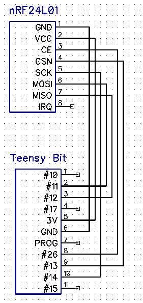

On left, the schematic for connecting Teensy and nRF boards. On right, the schematic for connecting Trinket and nRF and MPU boards.
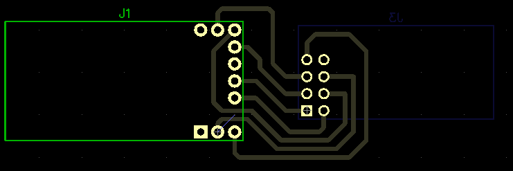
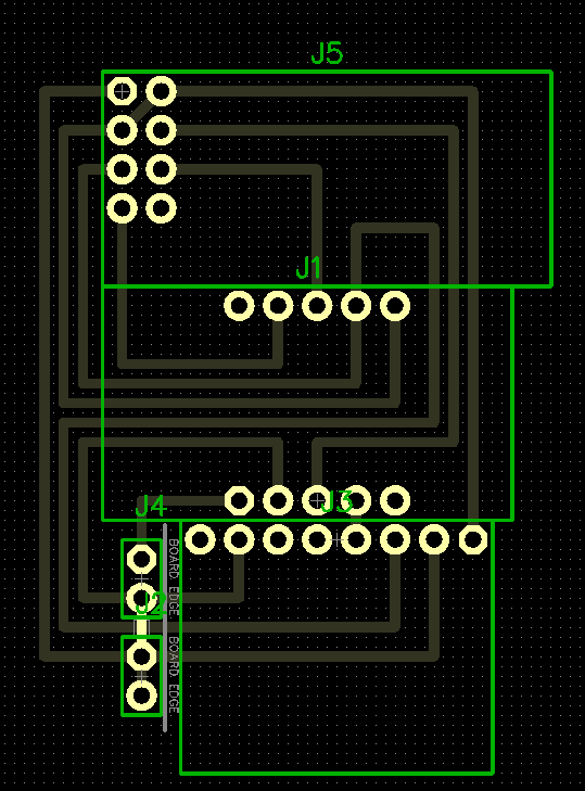
The routed PCBs, for Teensy and Trinket.
I bought a CNC router kit on ebay for under $200 to mill these PCBs. I was impressed with how inexpensive it was. The kit took about 2 days to assemble and test, and is working surprisingly well. It is not the most rigid machine, but it is amongst the most rigid ones of this price range and design. It is a very capable platform especially given the price, and with the widely spaced traces I am using here it performs well. Feed rates of 36-120 mm/min and 24 mm/min plunge seem to work well (with the spindle speed at 1000 relative voltage units, which is probably 7000 RPM).
The conversion from excellon or gerber files to g code for the router was done using the open source FlatCAM. The g code is then sent to the router GRBL controller, using the software that came with the router (which is just recompiled grblControl, with the title changed to something Chinese).
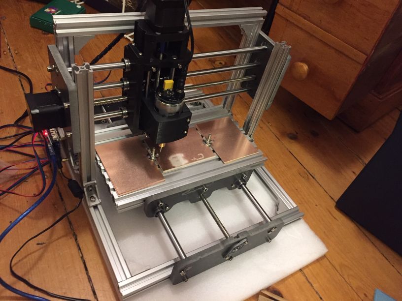
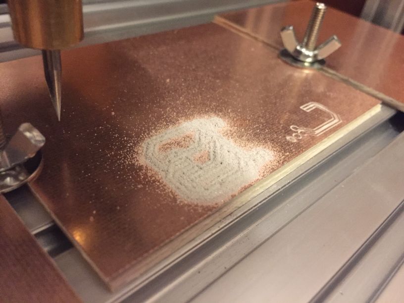

The assembled router and the first milled PCB.
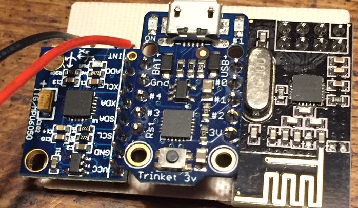
Initially I had purchased surface mount nRFL2401 modules. These were a pain to solder, and eventually turned out not to work at all - a risk inherent in ebay purchases. I would not recommend the surface mount modules, if only there seems to be a junk batch being sold off, but also because they are so annoying to solder (it is not so bad for installing it once, but debugging a non-working module involving desoldering then resoldering is a huge pain). A subsequent batch of header pin modules worked right away, and this is what is used in the assembled circuits. Hot glue is used on the nRFL2401 and MPU6050 boards, so they are more rigidly attached to the base and not overhanging the solder support.
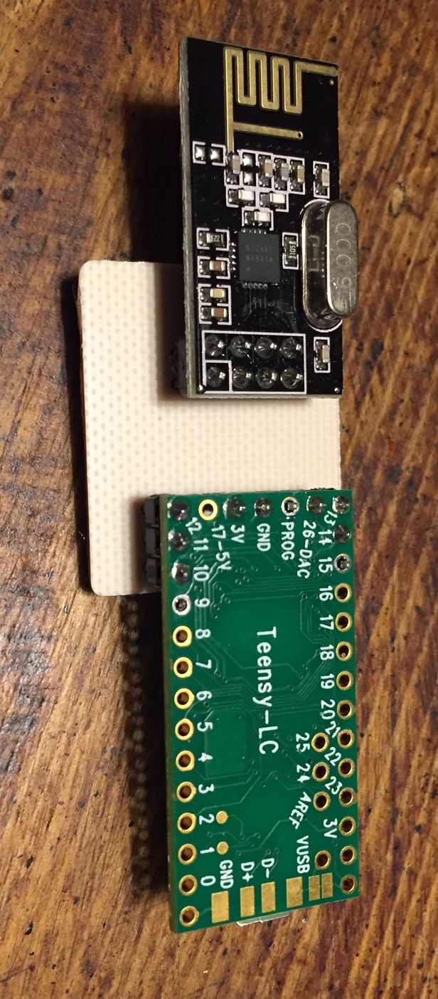
The Teensy LC connected to the nRFL2401.
The Teensy is connected to a radio with a milled PCB, and connected to an accelerometer by directly soldering to pins 2-9 (installation not shown) and then programmatically setting the pins to GND or VCC or floating, as required. If the radio module came in a package with a single header row instead of double, this project could be made with a Teensy and no custom PCBs at all by using this principle.
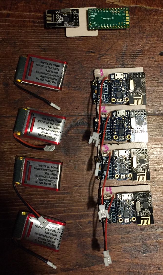
Finally the transmitting accelerometer boards are assembled.
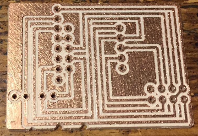
The remote PCB after milling and after soldering the modules together.
The Teensy LC acts as a joystick, and also interfaces via the USB serial port to allow easy modification of parameters, such as joystick mode, acceleration offsets, and timeouts, as well as to debug radio connections. The RF24 library with hardware SPI pins is used for interfacing with the radio, and the XantoI2C library is used for interfacing with the accelerometer (the Teensy has hardware I2C capacity, but the library is used here to help verify code for the Trinket). There are 7 modes, set by the Mx command where x is 0-6. 0 = joystick off, 1 = joystick from local accelerometer, 2 = serial output local accelerometer, 3 = joystick from radio accelerometer, 4 = joystick from 4 radio accelerometers, 5 = serial output radio accelerometer, 6 = serial output all radio data. Modes 1 and 3 operate using a single accelerometer, where the direction of the acceleration determines the direction of the arrow press. So, to get a down arrow, you would accelerate the board downward, and to get a left arrow you would accelerate it to the left. Mode 4 operates using the 3D vector magnitude of acceleration and does not depend on direction, with the arrow press determined instead by the accelerometer number. Code can be downloaded here.

Testing acceleration magnitudes with rapid movements, values above 10g can be observed (y axis is acceleration in gs, x axis is about 500ms of time). Thus the accelerometers should be initialized with the maximum range of +-16g.
The basis of determining button press from acceleration is a sort of timed hysteresis switch. When the acceleration exceeds a certain threshold such as 4g, the button is considered pressed, and it remains pressed until the acceleration is below another threshold such as 2g. This keeps from inadvertently activating the button repeatedly. However this is insufficient since with accelerated movements there is typically a second "rebound" period where a reverse acceleration occurs - the button press activated on the acceleration but then there follows a similar magnitude deceleration, and then the button presses are bouncy. Yet it should be possible to both maintain the button pressed down for a long time and rapidly press the button, if that is what the game requires. To permit this, there is a second threshold that is higher than the initial one, for example 6g. After a button release, a 10ms countdown timer is started, and within this time period to press the button again the higher threshold must be exceeded. After the 10ms, the normal threshold is enabled again. This ends up being very intuitive to use, because for a series of fast button presses one would use a "shaking" motion in which the acceleration magnitude will be up to double that of a single button press, so the higher threshold is readily crossed.
The Trinket meanwhile simply initializes the MPU6050, and sends data regularly. Each of the four microcontrollers is loaded with a firmware compiled with its unique radio pipe number (defined as MY_PIPE_NUM), so that they send on separate channels. Again the RF24 and XantoI2C libraries are used, with the radio connected to the hardware UART/SPI pins, while the accelerometer is bit-banged in software, since it is slower at a 400kHz maximum rate which the Trinket just achieves with 1us delay between pulses. While the top data output rate to the Teensy for this configuration is around 100 packets per second (achieving an approximate 10ms accuracy of button presses necessary for smooth gameplay), sending this much data is unnecessary and causes increased errors due to collisions with the other radios' packets. In a subsequent revision, the Trinket checks the upper bits of the MPU output, and only sends out a radio packet if there is a big change in acceleration (defined as about 1g). In the absence of a big change, it still sends out packets but at a slower rate of a few Hz. This minimum timing is implemented so that undelivered packets do not cause a long term incorrect input. The check of the upper bits is a fast operation that does not require converting the data to physical units, with this latter conversion done on the Teensy. For the purposes of this project it was seen as adequate to send a single byte of data for each axis (the MPU outputs two bytes on each, but the LSBs don't make a difference at the coarse sensitivity level of an on/off button press that is needed here), which makes for a shorter radio packet and thus reduces the chance of collision and error (note to make use of this the RF24 SetPayloadSize command must be used, otherwise small messages are padded with zeros). The MPU also outputs a temperature measurement which is read but not sent out. Code can be downloaded here.
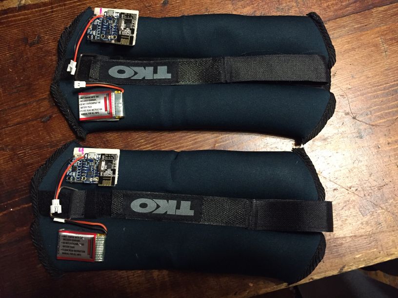
The completed set of boards with batteries, and how they are attached to wrist bands.
The concept works as expected! I recorded a video of using the single-accelerometer mode, which can be viewed here (44 MB). The four-accelerometer mode also works well, but I am not too proud of my dance skills so I didn't make a video of that. While it's a fun build, playing technical charts is not very practical in four accelerometer mode, because it is difficult to gain adequate control with the leg accelerometers while supporting body weight.