On a few occasions I have taken photos of the same subject at different times or from slightly different angles (including microscope images of samples over time, as well as landscapes during the day/night). The goal of this program is to align two or more photographs such that the subject appears in the same location on the screen. Having the images aligned this way allows for easy identification of changes between the images.
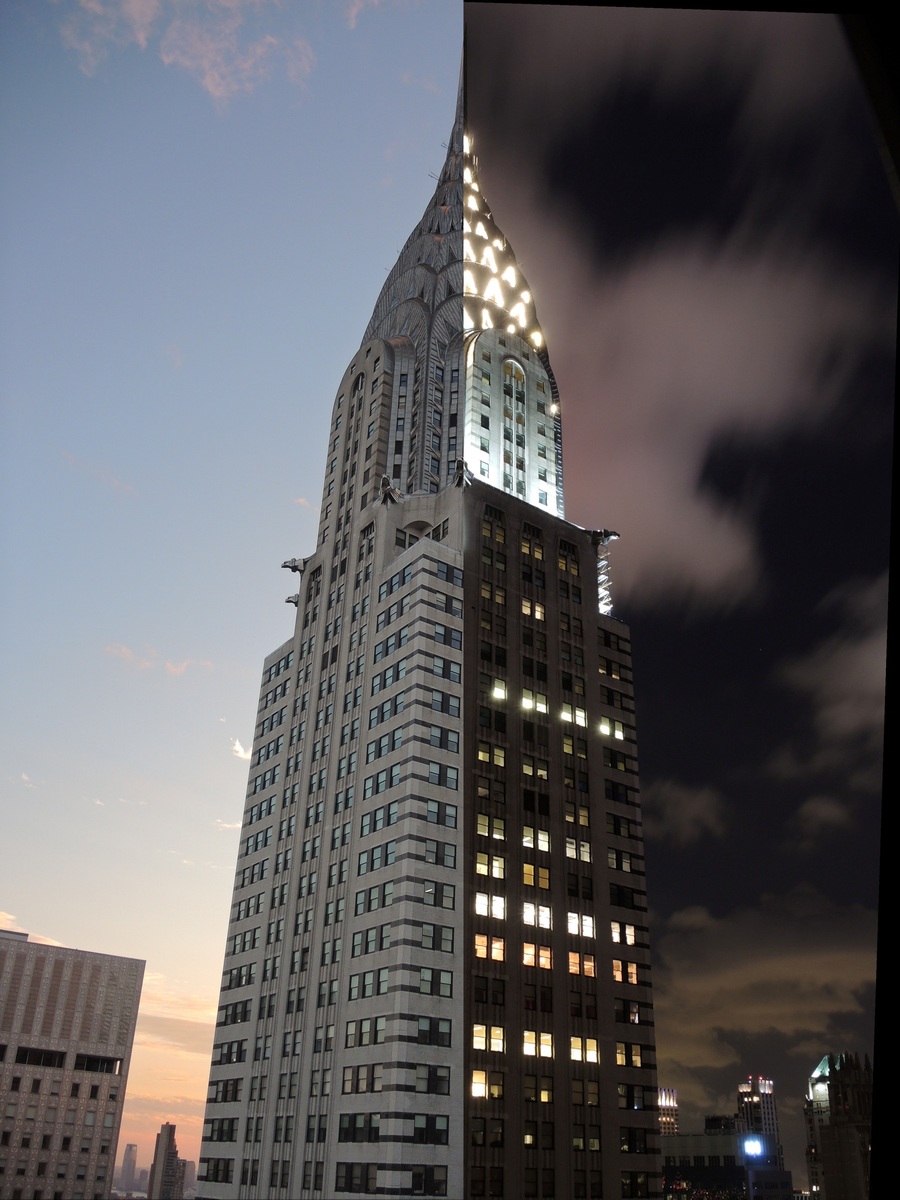
An example of the image aligner. This image is made by combining two separate photographs, after they have been aligned to almost pixel precision using the software.
The program operates largely through a click-and-drag interface. Internally it is based on the Image Straightener code, and even keeps the same namespace. We note a few limitations before starting:
As an example, we will align two photographs of the Chrysler Building, one during the daytime and one at night. They were taken from a similar location but with slight differences in angle of the camera.
Press the Load Reference button and select the reference image. The reference image is one which will be unaltered by the program (subsequent images will be altered to align to the reference) and which will determine the pixel dimensions of all output images. It will show up in the window along with a red circle and a green circle.
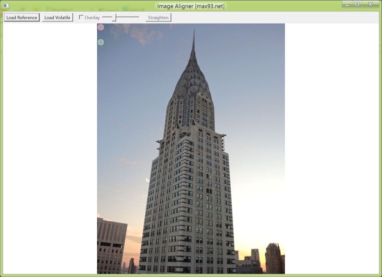
A reference image is loaded in the program.
Find two well-defined points in the reference image, such as corners and intersections of lines. Gradual or blurry edges will prevent pixel precision in the alignment. Then position the red and green cross-hairs (by clicking and dragging) over the two reference points. Clicking once within the cross-hair area will position the center at the point of the click.
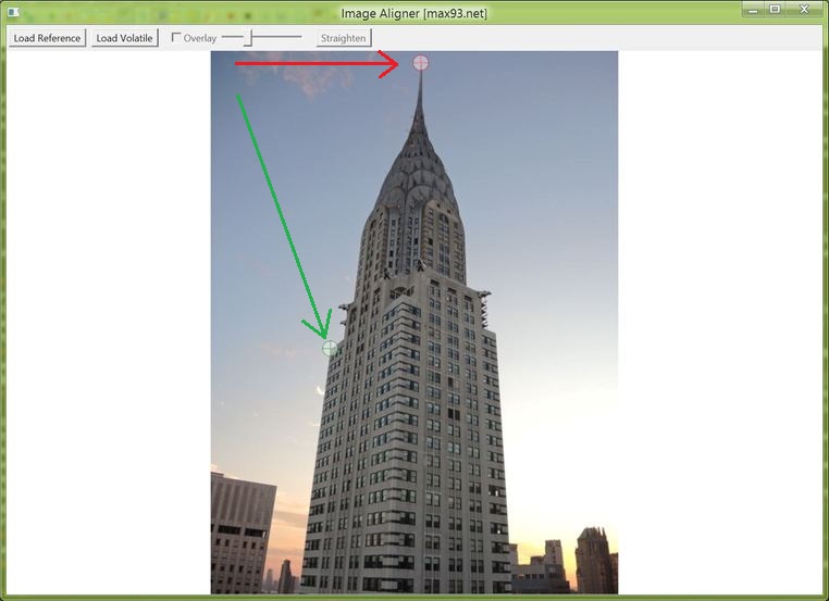
The red cross-hairs are placed on the top of the building, and the green cross-hairs are on one of the lower building edges. Arrows were added to show movement of the cross-hairs.
Press the Load Volatile button and select an image that needs to be aligned to the reference. The image will appear on screen. Then once again position the red and green cross-hairs on the same features in the image.
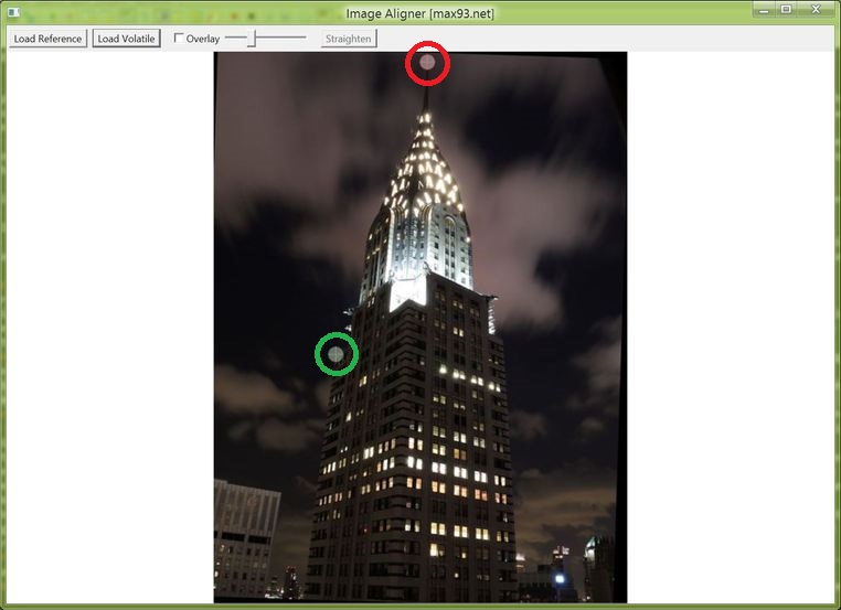
The night time photo has been loaded, and the red and green cross-hairs were set on the photo to match the same features as in the above step. The cross-hairs have been emphasized with big circles.
At this point check the 'Overlay' checkbox, which will overlay the reference image - with transparency - on top of the currently visible image. (You may recall that the reference image file is never altered, it is only shown here as altered to help with alignment.) Use the associated slider to adjust visibility of the overlaid reference image. If the cross-hair points were correctly selected, the transition between one image and the next should be smooth. Slight changes in angle of foreground objects and of objects affected by lens distortion are to be expected. If there are significant deviations, it is possible to drag the cross-hairs to correct this. If that is not sufficient, it may be necessary to restart from step 1 with different reference points.
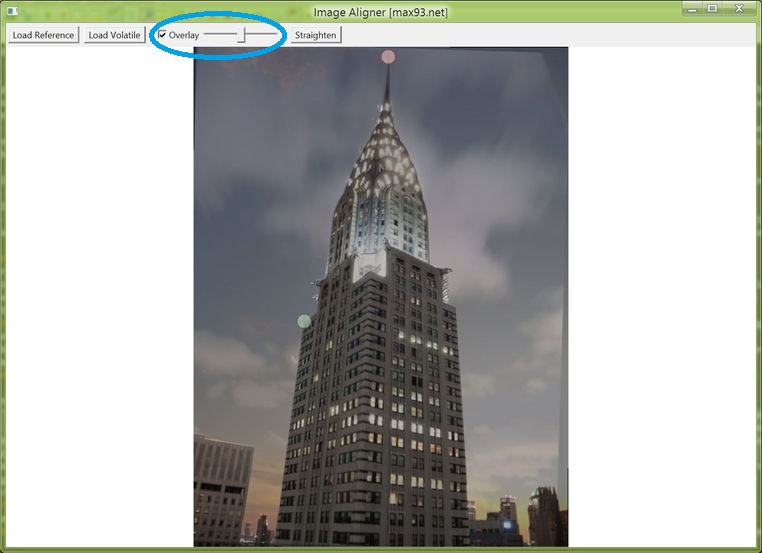
The daytime and nighttime images are overlaid and visually the transition appears smooth. Note the darkened rotated rectangular border around the edges that is due to the rotation of the volatile image's edges during alignment.
Clicking the Straighten button (I already mentioned this is based on the Image Straightener code) will apply the transformation to the volatile image and give the option to save the resulting file under a new name.
It is possible to align multiple volatile images to a single reference image. To do this, press the Load Volatile button again and repeat from step 3. All output images will have the dimensions of the first-loaded reference image and will be transformed to match it. It is theoretically also possible to press Load Reference again in which case you would need to repeat from step 1, but some bugs might make it preferable to restart the program.
Here are some other comparisons of combined day/night photographs from New York City showing the effectiveness of the algorithm:
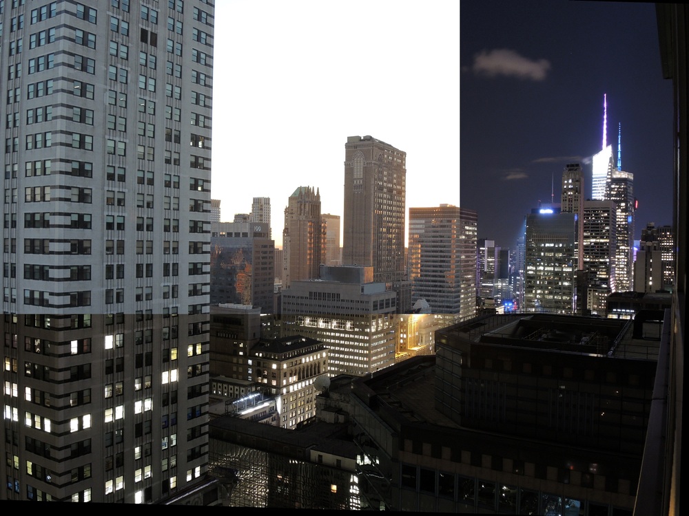
The inset on top right is during daytime, rest is nighttime.
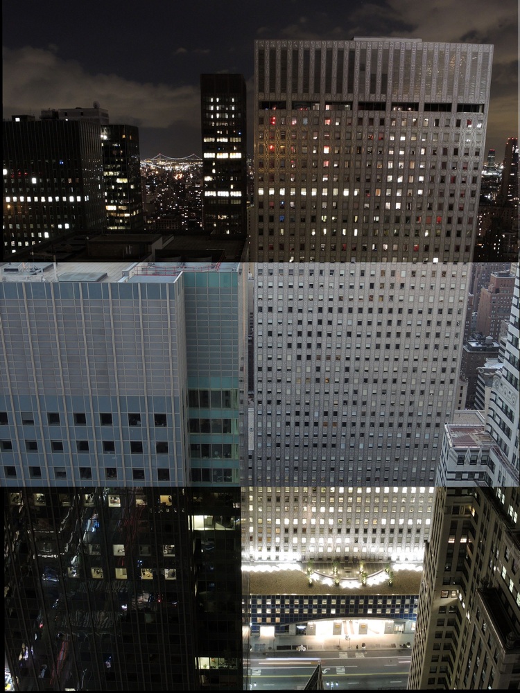
A daytime image is in the middle. Note the surprising reflectivity of the building on the left at night.
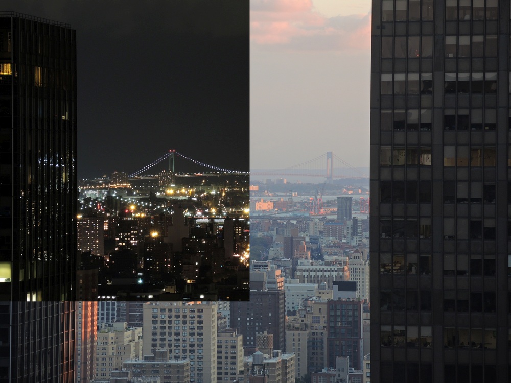
Combined view of the Brooklyn Bridge.
First we are interested in what it will take to 'align' two images. Starting from a physical basis, defining a photograph in 3D space requires these parameters:
So overall we have 7 unknown parameters. However some thought reveals that for different camera locations the photograph will be of physically different features so no computational algorithm can match up such photographs without external data (there is a degeneracy between camera location along the pointing direction and camera zoom level, making a total of 6 unknown parameters more accurate but this does not change the argument). Thus we assume a nearly constant camera location which removes 3 location parameters, leaving just 4 parameters. These are represented by the red and green alignment points (xr1, yr1) and (xg1, yg1). The mechanism of the camera's operation (projection) in 3D space, as outlined in the Image Straightener article, means that theoretically an incremental change in camera pointing direction will result in an incremental linear translation of the resulting 2D image, making this program's operation plausible.
Alternatively from an intuitive basis, to align two images at least one point must match in both. So in the Chrysler Building case, we know that in the aligned images the top of the spire should be at the same pixel on the screen. So leaving one image unaltered, we can just move the other image in x and y such that the top of the spire is appropriately located over the first image. This means we need 2 parameters for that point, (xr1, yr1). Next if the two images are at the same zoom level, we can match two angled lines to have the images match. But generally we expect slight differences in zoom, as well as rotation, and matching a second point will satisfy both of these - the distance between red and green points will define the zoom level and the angle of the line between the points will define the rotation. Thus another point (xg1, yg1) will be sufficient, making for a total of 4 parameters.
Now to reach a conceptual understanding of the transformation, consider the effect of an origin on translation and rotation. Translation can be defined independently of an origin in an incremental way (any point can be assumed to be the origin for calculations), but in rotation the origin is a special point that is not altered. However we are concerned with matching the angles of lines, and in this sense the origin of the rotation does not matter as long as it is combined with a translation. It also does not matter in which order these operations are applied. Scaling is similar to rotation in that the origin is not altered, but when combined with translation the origin used does not matter.
In the considered algorithm, the order of these operations is hopefully intuitive: First, translation is used to cause the red points to match. Second, scaling is used with the red point as origin to match the distance between red and green points in both images. Third, rotation is used with the red point as origin to match the two green points. Mathematically the second and third steps can be accomplished in a single matrix transformation (represented by multiplication in the complex plane). The first step is similarly represented by addition in the complex plane. Thus we require parameters (a, b) that represent translation offsets and also (c, d) that represent scaling and rotation. The transformation is then as follows:
[xr1 xg1  = [c*cos(d) -c*sin(d) *[xr2+a xg2+a
 yr1 yg1]    c*sin(d)  c*cos(d)]  yr2+b yg2+b]
The executable is available here. The installer file (which will also install .NET framework if it is missing) is available here. The source code is available here.