After the untimely demise of the Hoverboard's motor controller 'MC', I decided to improve on that design and test out another approach with the 'MC2' motor controller. A bit of inspiration for this design came from the RageBridge 2 layout.
After the difficulties with high current wires and heatsinks on the MC controller, the MC2 is designed to require minimal components and assembly. This is accomplished through these design decisions:
While for MC I used Eagle, for this controller I used DipTrace and liked it much better. It highlights any errors on the board in real-time and has other useful features (such as automatically showing trace length and dimensions of pads, as well as a 'ruler' tool) that resulted in no need of board modification after fabrication (for MC there were at least three big errors of traces crossing or improperly connected - they were just harder for me to find with the interface in Eagle).
This is still a dual-motor controller, based on the TI Delfino F28335 with DRV8301 driver ICs, supporting 12S (48V, maximum 60V) operation with up to 20A per motor (30A and above results in hardware limiting). Unlike the MC it can sense voltage on each phase, making it possible to program as sensorless or sensored as desired. It accepts 3 hall effect sensors per motor, and interfaces with a PC over a serial connection. An on-board potentiometer, buttons, and LEDs allow adjustment of parameters without a PC. It accepts two throttle inputs (and has no IMU) to drive the motors, and senses current on two lower legs of the half-bridge for each of the motors. In the MC, current was sensed on the phase output - the change to a shunt resistor on the low side (that is, between battery (-) and the FET drain) results in a simplification in the circuit but a stringent synchronization requirement for measuring the current accurately, such that the measurement takes place when the low-side FETs are active. This synchronization should be easy enough to achieve with the F28335.
The board gerber files are sent off to 4pcb, and we fit an extra power board and thermometer board (for another project) into the space previously taken up by the MC controller. The board is cut into four sections, two of which are mounted vertically.
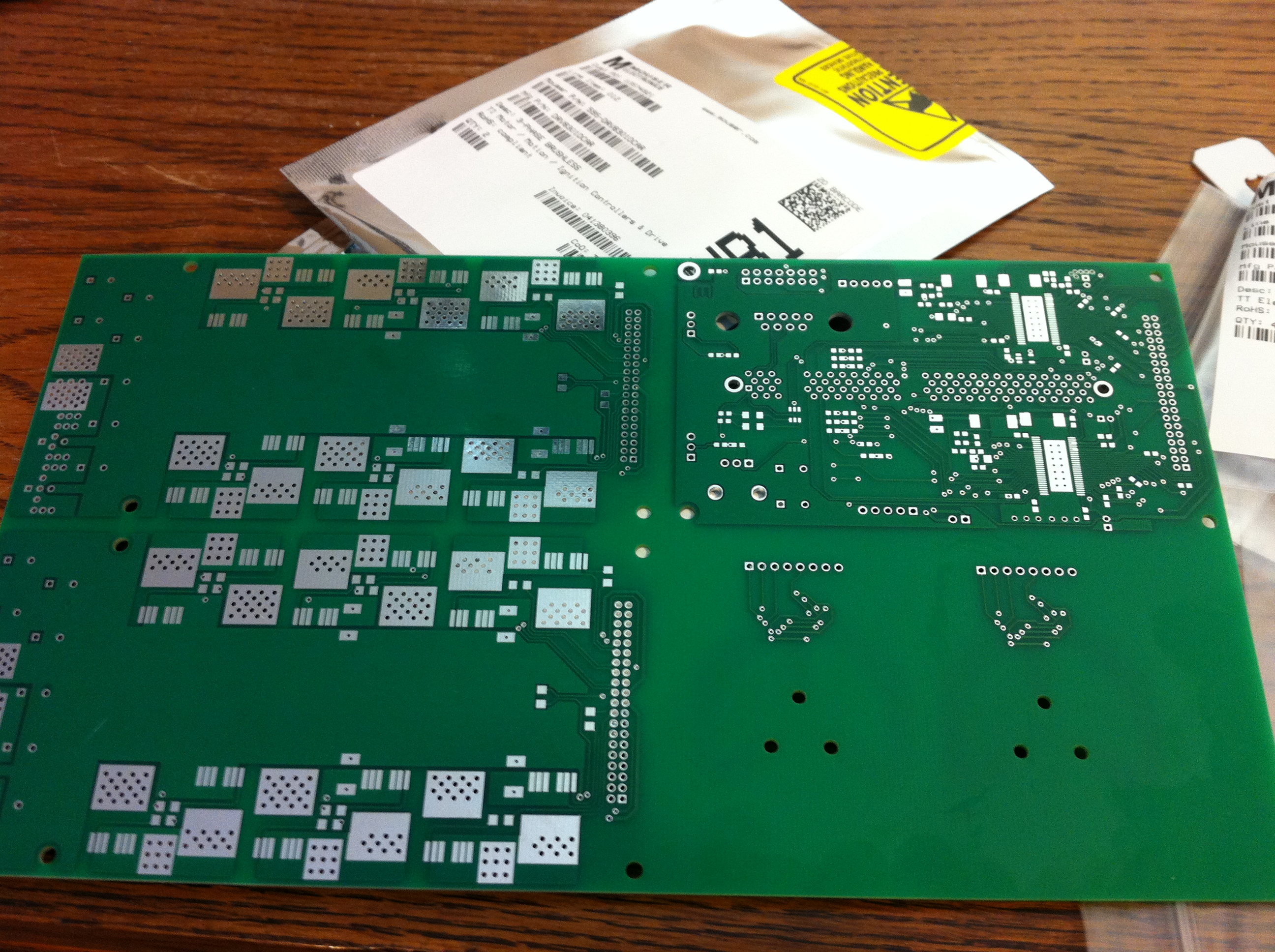
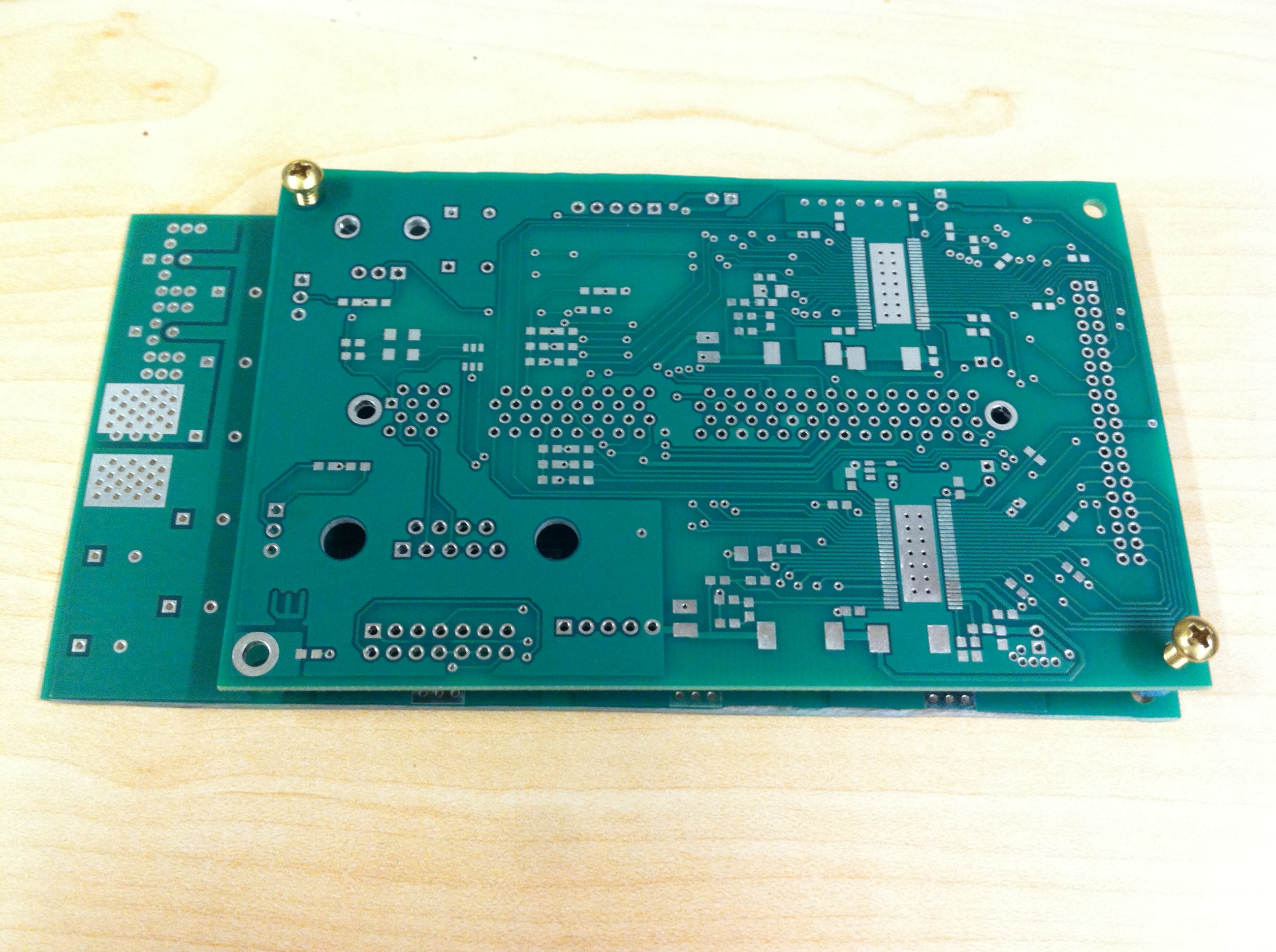

The controller is based on two boards which were purchased as one board (left) that is then cut using a rotary tool. The two boards are connected to get an idea of the final appearance (middle). The size of the MC2 controller is compared to the MC controller (right).
Then the power components (capacitors and MOSFETs) are installed, along with a single 5V buck converter based on the DRV8301. Insulating plastic spacers and bolt 'sleeves' are 3D printed since that size was not readily available. One of the bolts is not insulated, it will connect the controller ground to the metal heatsink under the controller through a varistor.
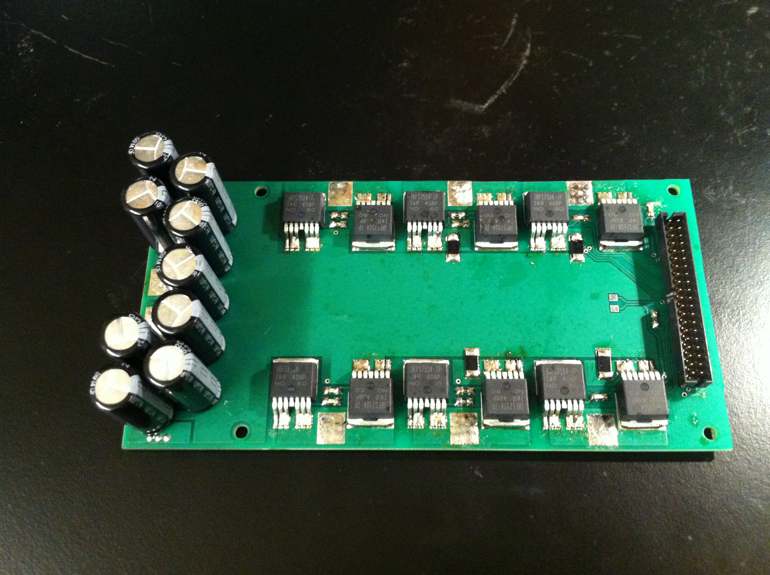

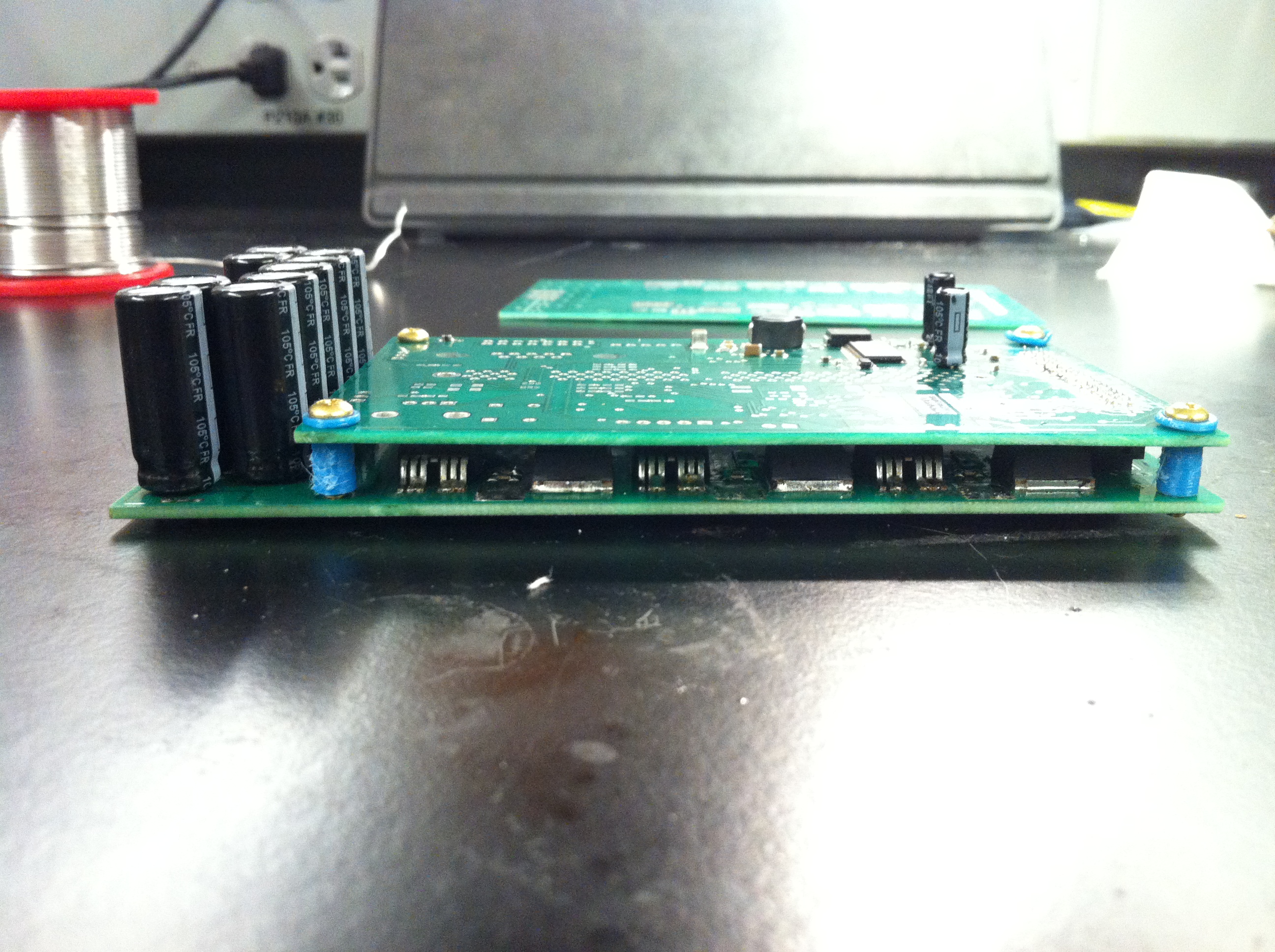
Left, the power board is complete. Middle, the logic board has one of the DRV8301s and the buck converter installed. Right, a side view of the board.
The second DRV8301 and other parts are installed (the most obvious are the potentiometer and buttons and headers). The power supplies are successfully tested resulting in about 10 times less idle current that with the MC dual power supplies. Unfortunately along the way a precision 3V supply IC (used so the ADC and the shunt resistor amplifiers have the same reference) blew up because I forgot that the Vin of the IC should be 5V and not 48V. This oversight resulted in a momentary pulse of 48V to logic inputs on the DRV8301 which later prevented its proper operation in driving the MOSFETs, although it could still be reached by SPI communication.
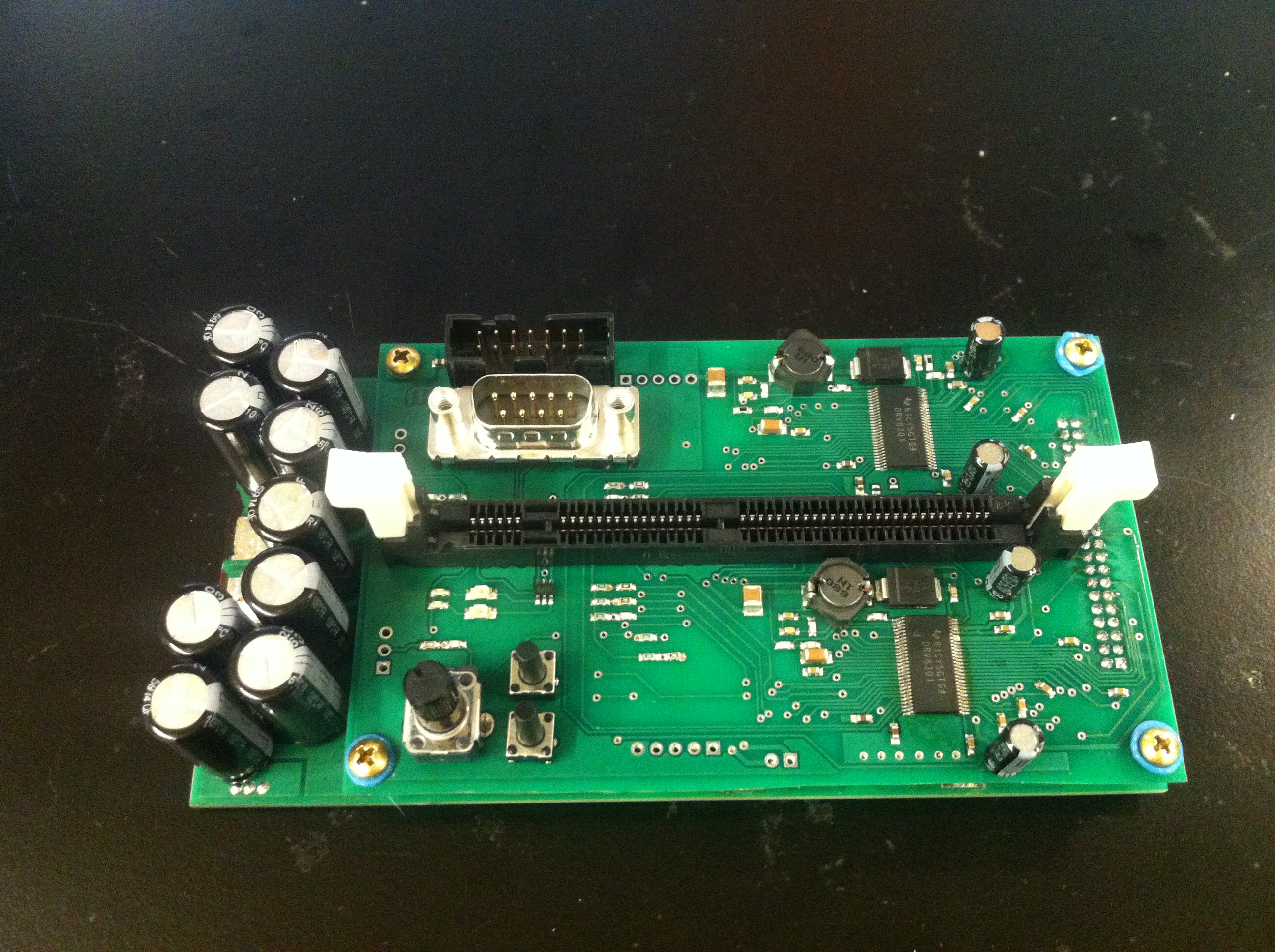
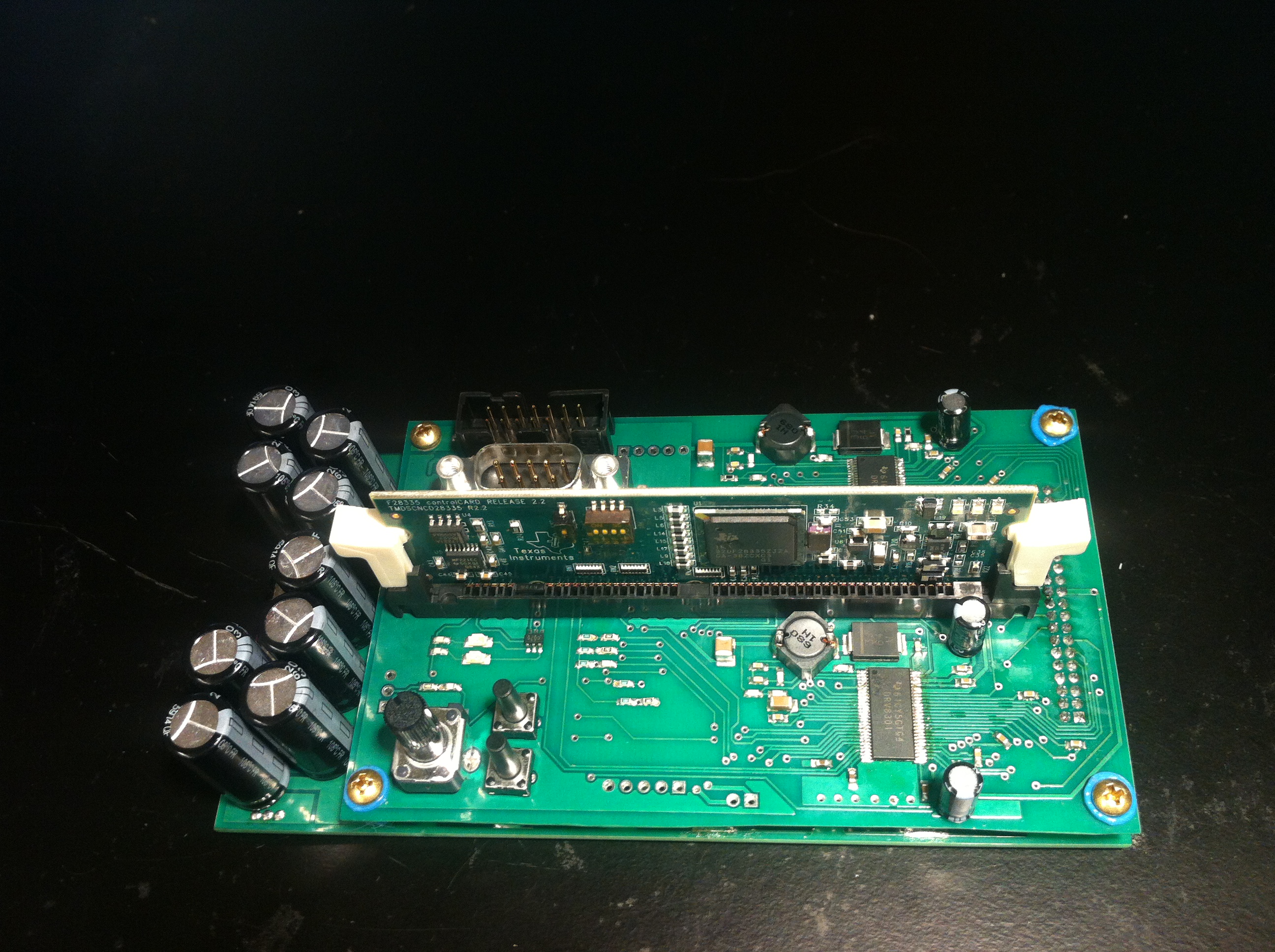
Left, the logic board is finished. Right, the processor card is installed, ready for programming through the 14-pin JTAG header.
Finally power wires are soldered onto surface pads, each of which has vias to the opposite side of the board for increased mechanical rigidity/preventing peeling-off of the pads. Throttle and hall effect sensor wires are soldered to the logic board.
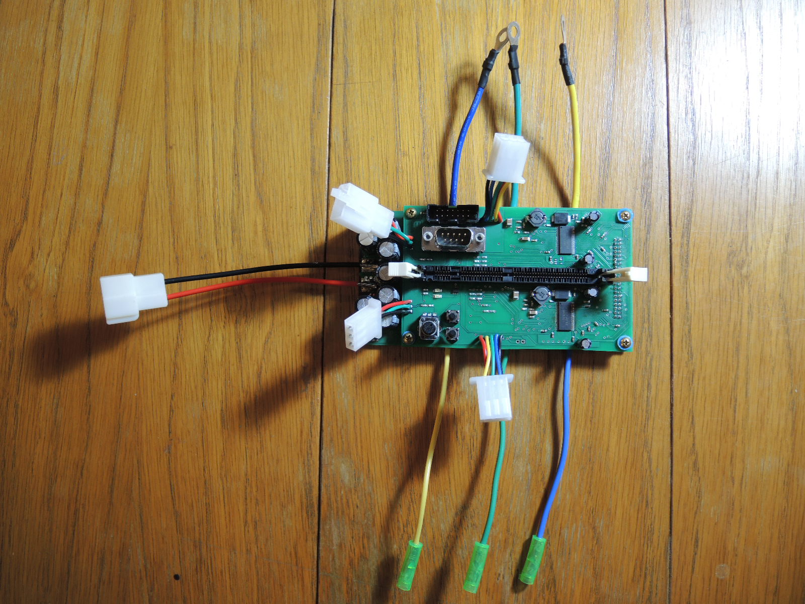
The finished MC2 motor controller.