In this project, I attempt to design a vehicle that is controlled by leaning in the direction of travel, which responds by varying the acceleration rather than velocity. The idea arose while riding a crowded subway train in which I needed to shift my weight when the train was accelerating in order to stay upright. After a few stops I was able to match my leaning-over to the train's acceleration reasonably well, which was quite an exciting feeling as I could remain balanced at angles where I would have definitely fallen over had the train not been accelerating. Thus, the train's acceleration combined with gravity led to a total acceleration vector that was not perpendicular to the floor, and if I were to match the angle of this vector I could stand without needing to hold on to a handrail. The hoverboard project is a reversal of this concept, where I would be able to stand at any angle and the vehicle would alter its motion such that the acceleration vector would pass through my center of mass. I called this a hoverboard because I imagine this is how a real hoverboard would be controlled (also this method of control might give a feeling of 'hovering around').
Implementing this idea requires the following main components: a 2-DOF surface (meaning a platform that can tilt about two axes, independent of any ground contact surfaces), a drive system that is able to accelerate the vehicle to counteract the tilt of the platform (so at least 2 DOF as well), motors that can provide a high torque and high speed (the high torque enables the platform to tilt to larger angles, while high speed is crucial to allow reasonable operation in the acceleration-controlled mode - since constant acceleration means increasing velocity), and a controller system that can sense the platform's tilt and drive the motors in an appropriate way to counteract it.
The first design was a (conceptually) straightforward implementation of the above requirements - it had a flat rectangular platform (like a skateboard) balanced on a four-spring mount that allowed tilt in two axes, connected to a four-wheel base with four independent motors, each with its own controller and a main controller. Ths first issue arose when considering steering - whereas skateboards can use trucks for this, reliable operation requires that the steering angle of the wheels be controlled independently of the tilt angle of the platform (this is because the proportionality between the two is dependent on forward velocity - just like when driving on a highway the steering wheel is used only over a small range). In this design, this required an entire complicated assembly with another set of springs and a motor to adjust the steering angle. Furthermore, at high speeds the small skateboard wheels will not handle bumps very well, so they should be outfitted with shock mounts, which requires isolating the motors as well. Overall, the design appears too contrived to fulfill its intended purpose.
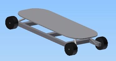
CAD of the first design.
An inspiration came from finding a 'segboard' video, in which a skateboard is connected to two large wheels positioned at its center, allowing control of both acceleration and steering without any mechanical adjustments other than changing the speed of the wheels. This approach cleverly removes the springs required for the tilting platform, as the platform can now tilt about the central axis of the large wheels. Additionally, steering is much more straightforward and the problem with bumps is alleviated by the use of larger pneumatic-tire wheels. The only remaining issue is the questionable control of tilt steering, since the board is rigidly mounted to the wheels on both sides, so while tilting left or right to accelerate is easy, tilting forward or backward is counteracted by tire deflection, leaving only a limited range of allowed tilt angles. If the tires are moved farther apart for increased stability, getting a reliable tilt measurement will be quite difficult.
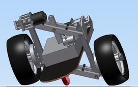
To account for this, my design has an additional pivot point on which the platform is attached, which allows it to swing freely in both the steering and acceleration directions. It has taken me a while to accept that this design is mechanically sound, but here it is important to remember that the controller will keep the platform balanced so freely-moving structures are acceptable (and actually necessary if tilt control is to be used). A more involved variation has the wheels also mounted to a pivot, such that on tilting the wheels would also match the acceleration vector (this would maintain the load vector perpendicular to the wheel axis). It took some work to maintain rigidity in this setup. Using a rigid axis instead simplifies the design but limits the maneuvers that the vehicle can undertake safely (this can be improved by moving the wheels farther apart).
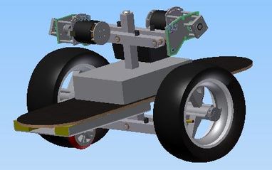
CAD of the final design.
Here are some additional images that help explain how the board can be tilted on two axes. There is also an animation (0.2 MB) available.
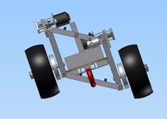
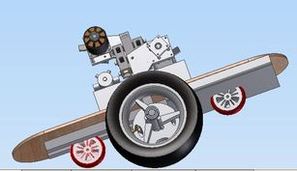
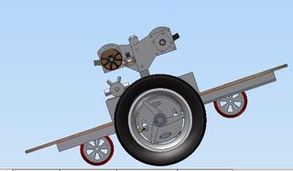
Four views of the board tilted to the left and forward. From left to right: view facing board in direction of travel with tilt along one axis, view from the side with tilt in both axes, view from an angle with tilt in both axes, and view from the side with tilt only in the travel axis.
As this was a complex design, the parts selection process led to quite a bit of frustration. Perhaps one mistake was relying too much on HobbyKing products, which was acceptable for the more straightforward quadcopter project. The data on HobbyKing usually contradicts itself, as well as the data on other products. A motor slightly more expensive than a "1500W" output claims "2400W" output, while a much more expensive model (that handles higher current and voltage levels!) is only "1800W". The motor testing curves are the closest resemblance to any 'real' data, but they were present only for one of the five motors I was considering. Overall it was a very disappointing experience, not helped by the discontinuation of higher-powered models with 10mm output shafts. I ended up buying the fairly expensive motors from Alien Power Systems, as they were used with success on SColton's tinyKart, who gave useful testing parameters on his blog. As much as I was looking forward to receiving them, I got another disappointment as they arrived damaged with nothing but a 'fragile' label in the box to protect them - here I would have much rather paid another $1 in shipping to get some foam in the box.
The next challenge was to find motor controllers that would be a reasonable choice for the application. My original design was quite similar to a quadcopter, with four independently driven wheels. The new design would require only two wheels, thus either the motors would be geared together to maintain the previously calculated power output, or there would be two more powerful motors (requiring more powerful controllers). For mechanical simplicity, I went with two motors, but this seriously limited the motor controller choices available in the RC-aircraft world. Furthermore, after additional reading and reviewing ride videos, it was evident that the sensorless control which is exclusively used for aircraft models is a poor choice for generating high torque at low speeds. This may have been passable with the previous four-wheel configuration because it could be kick-started to some extent, but with the two-wheel design this was unacceptable. Additionally, the hoverboard would require fine control of acceleration and braking torque, as well as the ability to reverse direction (so full 4-quadrant operation). Generally the HobbyKing grade sensorless controllers at best control the speed (most run open-loop) with no braking, and on the few that allow reversing the sensorless algorithm to do so is prone to issues. Racecar controllers would be a bit more appropriate for the task, but they do not reach the same level of power density. Also, the rated current values for all these ESCs are overly optimistic. At one point, I considered buying airplane ESCs and flashing them with software like BLHeli, which might also be modified to accept position sensors. However, reviewing the supported ESCs list revealed very limited choices for available high-powered ESCs, and I did not want to take a chance on spending a few hundred dollars since I had no use for the ESC unless it could be re-programmed. Additionally, this would require another controller (an APM 2.5, just like the quadcopter) which would also have to be custom-programmed...
So in the end I decided to build a custom motor controller. The controller would have an integrated IMU which it would use for balancing as well, removing the need for re-programming an APM. The controller would drive two motors, using sensor feedback, and would have current measurement capabilities to enable field oriented control (this is a way to accurately control torque, rather than speed). Also it would have components rated for the task (so as not to fail when I am in the middle of a road). In the end, this turned out to be an expensive (and ultimately fruitless) route but it was an important learning experience.
While on this discussion, I want to point out that the hobby ESCs are actually very clever designs (despite what my comments above may suggest), and are a good example of cost- and size-constrained devices. The problem I have is with the marketing, putting arbitrary numbers on the ESCs. So I would suggest to not trust values listed on sites like HobbyKing and buy directly from sites like Kelly Controller.
The motor controller is housed on one board but is designed to integrate multiple systems necessary for this particular vehicle. The following list gives an overview of the different 'modules' of the controller:
The above list includes sensors and capabilities that would not have been available easily or at all in a setup based on hobby-grade controllers wired together, providing another reason in support of taking the custom controller design route.
An external key switch, rated for 48V, makes a momentary connection when the key is inserted. The momentary connection power the K1 relay coil, which when activated charges the board's capacitors through four parallel 1k resistors R1, R2, R3, R12. It also simultaneously powers the 15V buck converter through three series 10 resistors R75, R76, R77 (in the final revision these resistors are shorted out since they tended to overheat). The motor controller, after powering up, will enable the OK1 optocoupler through a buffer. The optocoupler will enable a buck converter based on the 555 timer chip IC1, which outputs approximately a 50% duty cycle to FET Q37, which provides approximately 24V from the battery's 48V to power the high current relay coil (not shown). If the board then continues to provide power to the high current relay, the key can be removed and power will continue to be supplied even though K1 is deactivated. When it is time to power off the board, the opto-isolator OK1 is de-activated to remove the main power source, and the opto-isolator OK2 is activated to enable the relay K2 to discharge the main capacitors through the same four parallel resistors as used for charging. Due to possible risk of shorting during operation, the relay K2 was not used in practice.
While the vehicle is powered on, the buck converter based on the TI LM2576HV, IC29, provides 15V to the board which is used for FET driving. The SJ3 and SJ4 are virtual connectors since the logic section of the board is otherwise fully isolated. However for compactness these connections are made on the actual board. IC30 then provides 5V for all logic components. However the choice of IC30 is a poor one - it would greatly overheat and ultimately had to be replaced by a switching 5V converter that I had available.
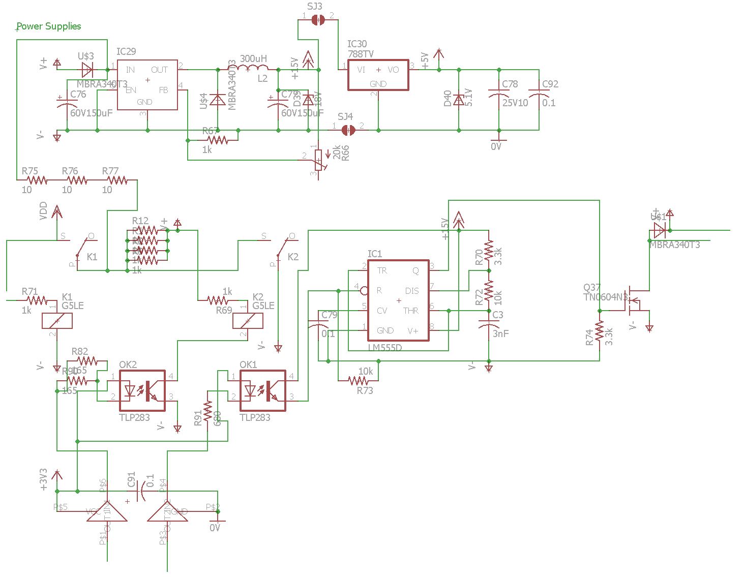
Power supplies schematic.
(2016 update: this is in many ways a dumb design.. it is shown for historical reasons but it would not be wise to replicate it) The TI Delfino TMS320F28335 chip is used to run the main code that generates the PWM pulses. These pulses are at a 3.3V level, and the chosen driver ADUM7234 accepts 5V input. Thus a 74HC04 inverter IC2 is used to convert the levels. Each leg of a half-bridge consists of three IRFB3006 MOSFETs in parallel to better distribute the current. Two of three outputs on each motor additionally have the ACS758 hall effect current sensors on the output. These operate better at 5V so an op-amp is used to convert to a 2.5V signal and provide high frequency filtering. (If I were doing this again, I would power the current sensors directly from 3.3V and remove the op-amp part.) The MIC4420 is connected to the ADUM7234 output to achieve a faster output pulse.
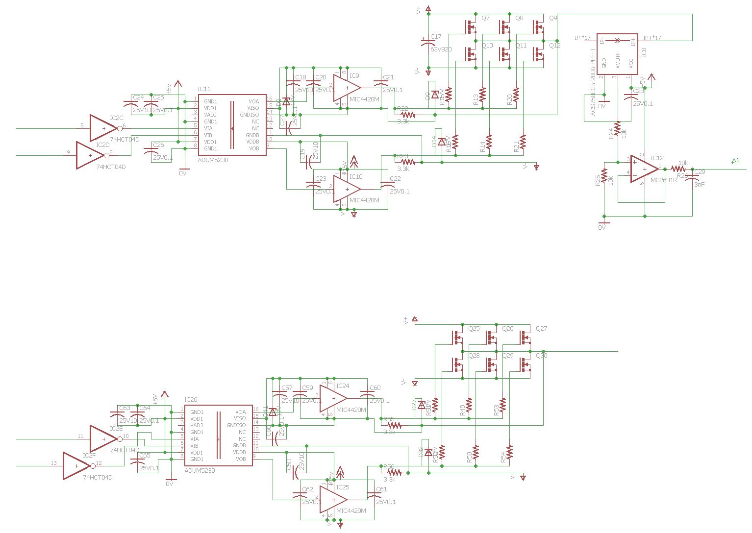
Inverter schematic.
The interface to the hall effect sensors is through a high frequency filter. The buttons have pull-down resistors. Buffers and voltage dividers are also shown. The IMU used to determine board angle is the surprisingly tiny BMI055. Also shown are two capacitive proximity sensors PCF883 which are intended to be connected to wires running under the board area where the rider stands. Initial tests show that this sensing method is adequate, but it is questionable for use over long periods (it may 'drift' or 'latch' over time), therefore it is not actually used by the processor to avoid accidentally shutting down while riding.
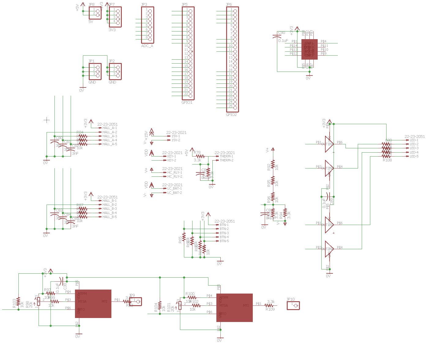
Sensors and connections schematic.
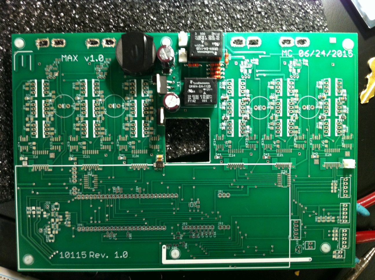
This motor controller might be unique in having a hole in the middle, so it is 'skewered' onto the central support column of the vehicle (though the more standard bicycle motor controllers sometimes have holes under components for convective cooling). The PCB area that used to be in the space of the hole is made to be the interface board, containing four buttons and four LEDs, and using 10 wires to connect to the main board.
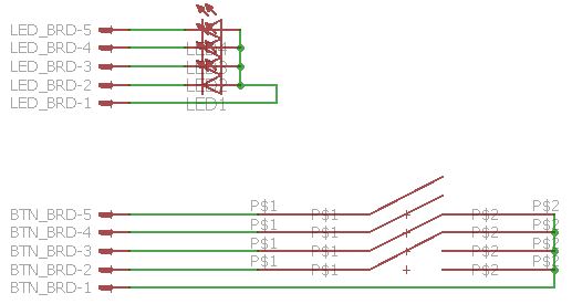
Interface schematic.
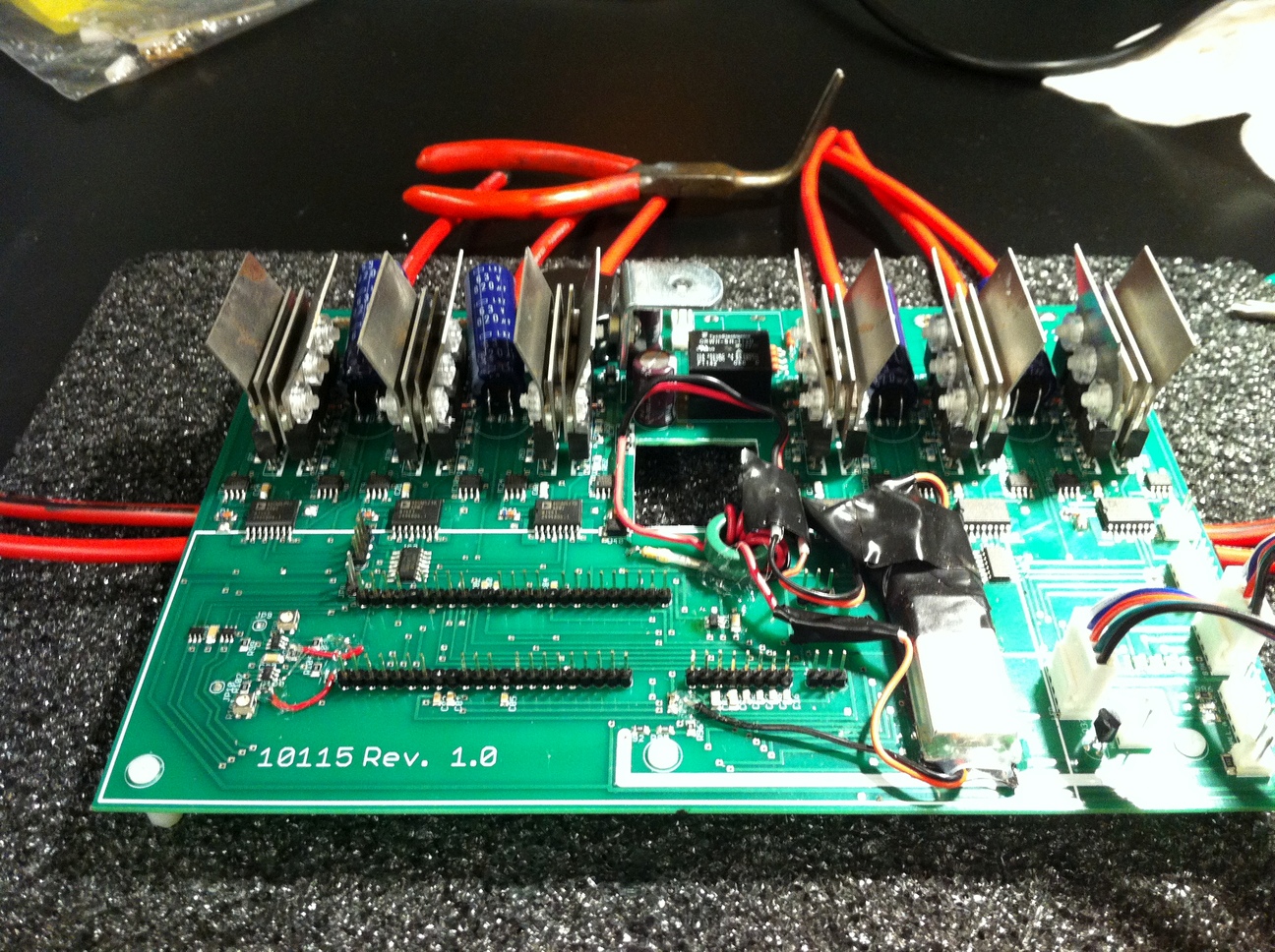
After putting together the above schematics and doing the routing, the board design is complete. One thing of interest might be how the high current connections are handled. Note the thick blue traces - over them I have added a mask layer (shown as diagonal lines) that will make them exposed like through-hole and surface mount connectors. The intent is to solder thick wires directly onto the exposed copper traces. To avoid 'peeling off' of the traces, I placed groups of 3x3 and 4x3 vias/holes in close proximity near the edges of the traces. After hand soldering the thicker wires, these holes get filled with solder and provide a mechanical interlocking with the board material that prevents forces on external wires from being applied to the trace itself.

Routed motor controller board.
All surface mount components were soldered using a hot air tool and solder paste. All through-hole components were soldered with a soldering iron. The first step is to cut out the central section of the board, which will be used to hold the buttons and LEDs.
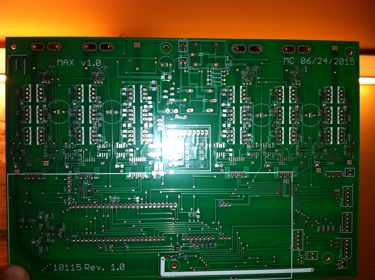
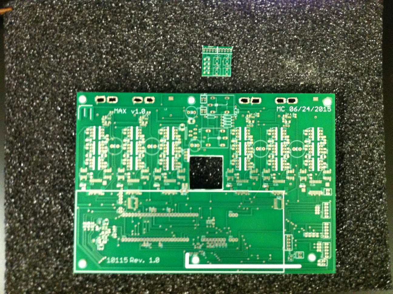
On left, the PCB as received, and on right the central section has been cut out using a rotary tool with an abrasive cutting wheel.
Second, the power supply components are installed and correct voltage output is tested. The LEDs on the interface board are also tested. Once this is successful, the board housing the board for the CPU (part of the TI Explorer kit) is installed. At this point USB communication with the controller can be established under its own power.
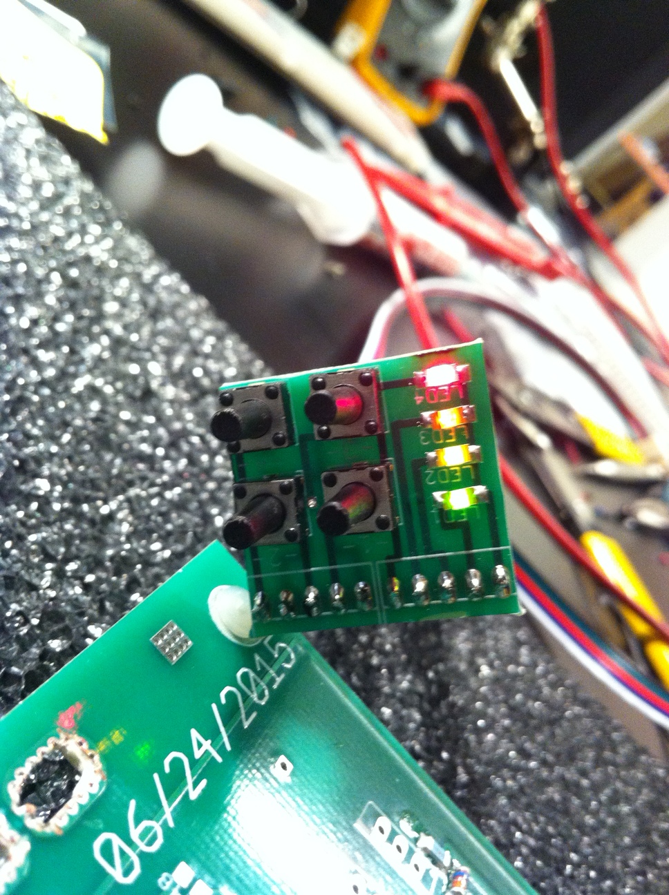
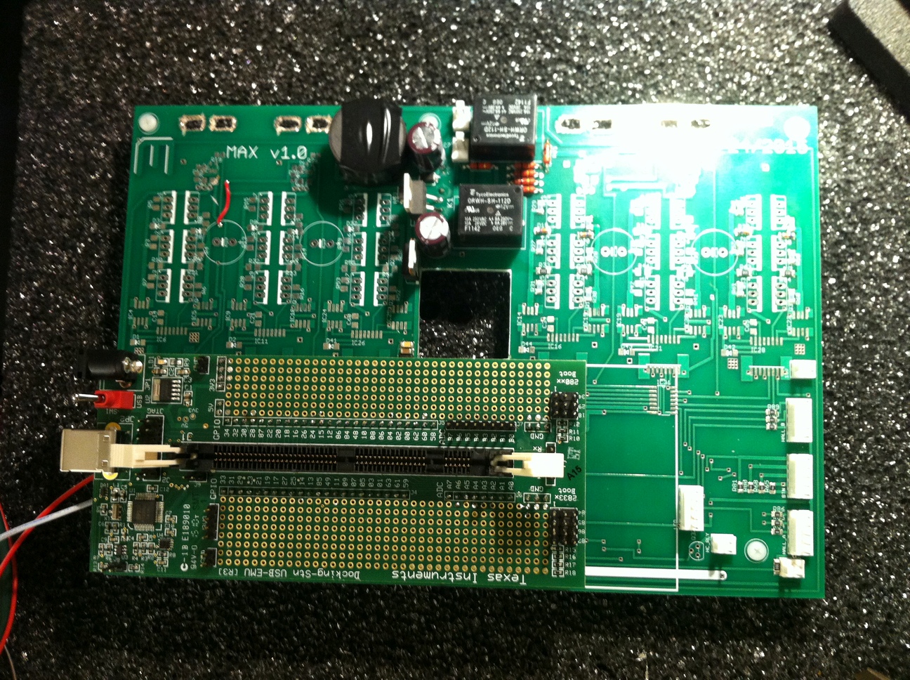
Initial component testing. In the last photo there is already an 'oops' red wire due to an embarrassing short between +5V and GND.
Third, the resistors, capacitors, and diodes in the MOSFET driving section are soldered. Additionally components for the high current relay coil buck converter and the pull-down resistors for buttons are installed.
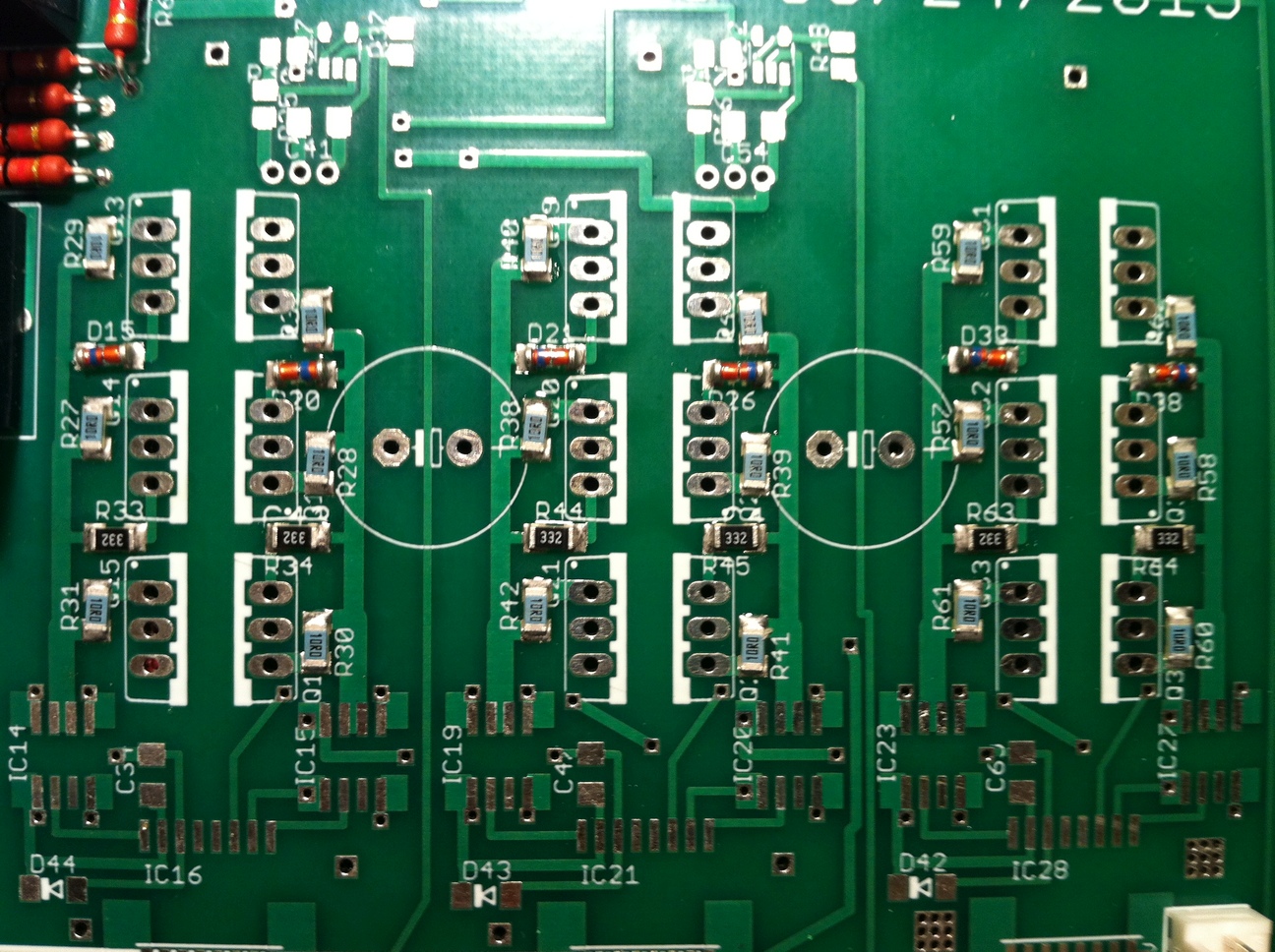
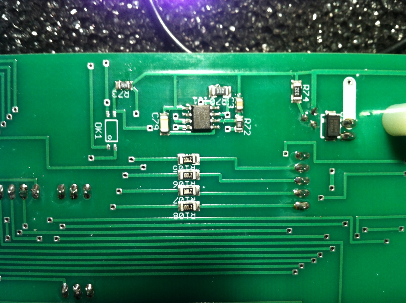
Close up of MOSFET and buck converter components.
Fourth, the MOSFET driver ICs are installed and powered on. At this point it was evident that the power supply design was not well thought-out. The isolated gate drivers draw a sizeable current even in standby to maintain a driving voltage on their output. While the 15V supply handled the load well, adding a 'heatsink' in the form of a steel plate still resulted in a fairly hot IC. However the 5V linear supply would readily overheat. Therefore it was replaced by a 'BEC' which is an independent switch mode converter that outputs 5V. Unfortunately this replacement makes the board look messy (there is even more to come). One thing that might be of interest is that on some BECs like this one, there is a jumper to select between 5V and 6V output. As I suspected, one of the pins is the voltage feedback used by the switch mode IC of the BEC, and another is connected to a resistor such that placing the jumper slightly shifts the feedback and therefore the output voltage level. However this also means that connecting that pin to the output voltage through an external resistor will allow variation of the BEC output voltage well outside the 5V to 6V range. In this case I used a high value resistor to make the voltage output closer to 5.00V. Another pair of 'oops' wires is added to supply power to the proximity sensors.

All components except for the MOSFETs have been installed.
Fifth, the high current wires are installed. To test the board's functionality at first small connecting wires are soldered on to pads that will be later connected by high current wires.
Left, the board is wired for testing. Right, an example of thick high-current wires to be used in place of the test wires.
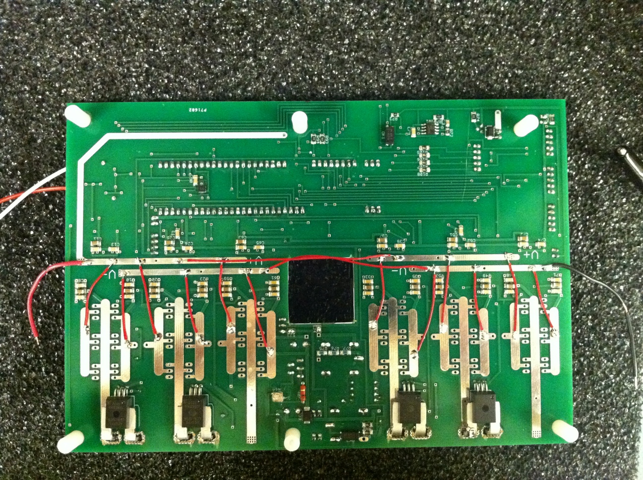
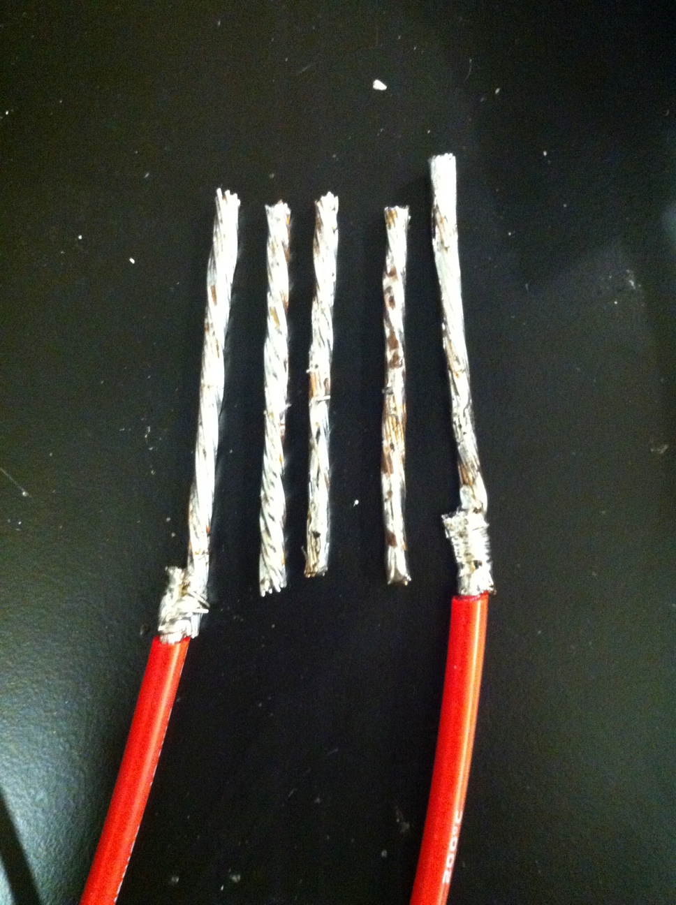
After soldering bare wires for the common connectors in each leg, a wire 'harness' is put together to distribute a single battery input into six different half-bridges. One annoyance is that the (-) wires have to go over the (+) wires, and these wires are very thick and barely bend. The 'harness' elements are done by first wire-wrapping the exposed ends of two wires and then applying solder generously. This whole process is very annoying and slow.
The thick wires were slowly soldered on to the exposed traces.
Just when the controller looked almost ready to be tested, another issue occurred. The motors I bought were sensorless, and I was planning to put external hall effect sensors so they could be driven in sensored mode, which is better for operation at low speed and starting from standstill. However the hall effect sensors I bought, the DRV5053, are linear (analog) output as opposed to 'switch' where the output is either LOW or HIGH. So to get a digital signal I put in 6 comparators that would center around the zero-field output of about 1.5V. If you decide to add hall effect sensors to a motor, make sure they are of a 'switch' type since such sensors also exhibit hysteresis which cannot be added to the linear sensor without external electronics (the hysteresis is useful for preventing noise due to the comparator in low speed operation).

Another mess of wires underway, and I am becoming even less certain of the possibility of completing this project.
Now the MOSFETs and capacitors for one motor are installed and the controller is taken for its first spin. The first test was completely open-loop and very inefficient, but did get the motor to spin (video 13MB).
The board is ready for controlling one motor.
With the first test successful, the MOSFETs for the second motor were added in to finally complete the controller board. One annoyance that emerged during the testing that followed was the difficulty of interacting with the controller. At this point there was no throttle input (this was not part of the design since the intent was to control the board solely through tilt angle) so I could only use the four buttons to control the motor. If you decide to design a controller I would recommend providing an easy interface with a 'high resolution' input method such as a throttle, potentiometer, or rotary encoder, as well as buttons for simple actions. Even with a poor ADC a potentiometer can immediately select one of ~100 values while a button can only select one, so for precise adjustments of timing/power/other parameters the former is a much better choice. Additionally the throttle/potentiometer provides some basic tactile/visual feedback of the selected value. As an attempt at a better interface, I connected a Turnigy receiver to the board, which I later replaced by a potentiometer for greater convenience.
All MOSFETs are installed and a Turnigy 9X receiver is connected as a test.
The final touches are put on the controller. Heatsinks are added to the MOSFETs, with insulating plastic spacers and plastic bolts since the back-to-back transistors are on opposite sides of the half-bridge. Then the empty space in the middle of the board is put to use as it is 'skewered' onto the central aluminum tube of the vehicle frame.

Heatsinks are added onto the board. Then the fit of the board is tested in its final location.
A test with sensor feedback is then carried out. The controller is connected to a brushless bicycle hub motor because that is already assembled with hall sensors, while the hall sensors for the hoverboard motors are not ready at this point. My controller is compared to a regular bicycle motor controller that came with the hub motor, and at full speed both draw approximately the same current (0.64A vs 0.56A at 48V, the regular controller is more efficient due to some synchronization problems in my code as well as increased idle current draw in my controller due to the isolated drivers).
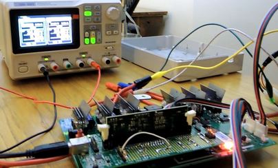
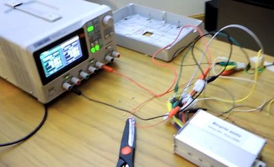
Setup for comparing my controller (left) to a commercial controller (right).
The effects of field oriented control (FOC) in reducing 'ringing' in the stator is very easily noticed when both controllers are used to accelerate the same bicycle wheel - compare the videos for the commercial controller (7.2MB) and my controller (10MB). You may notice a periodic buzzing sound in the second video, that is an early sign of the synchronization problem that will eventually lead to the destruction of my controller when higher speeds are used (this is also why in this test the wheel speed is slightly slower than with the commercial controller). Except for that sound, the electrical commutation is silent with FOC (it helps that the PWM is at 18kHz). I was also able to successfully demonstrate four quadrant operation - accelerating from standstill, then actively decelerating and reversing smoothly through the zero-speed point (some brushless controllers claim to have 'regenerative braking' which does not necessarily imply four quadrant operation - regenerative braking becomes less effective as the speed decreases while with FOC control it is possible to maintain a high decelerating torque by driving the motor in reverse if required). Unfortunately I did not get that test on video before the motor controller broke during the high speed test.
This is probably the most fun part of the project - to get the controller to actually work properly and the vehicle to balance. This is technically two tasks, the first mostly electrical in nature and the second mostly physical in nature, but both require programming and for optimal use of the processor I am implementing both simultaneously. The processor I used in this project is very powerful - TI's Delfino F28335. It runs at 150MHz and includes a FPU, hopefully enabling cycle-by-cycle control of PWM widths during runtime (that is, the control loop runs as fast as the PWM frequency)! TI provides a fairly extensive range of examples (although it seems their more recent example code has less and less comments, which is an unfortunate trend) for setting up field oriented control and space vector PWM generation. To start, in a basic interrupt running every PWM cycle, an assumed electrical speed is added to an internal rotor position variable, and then the PWM duty cycles for the three phases are determined.
To handle all the different inputs during runtime, it will be necessary to use multiple interrupts. The first interrupt, on every PWM cycle as described above, is useful to start ADC measurements of the currents (since at this point it is guaranteed that no switching transients will occur), and also to update PWM duty cycles for true cycle-by-cycle control. However it has to execute quickly, and thus the amount of processing should be minimized. This is done by calculating other important quantities in other interrupts, which are then used by this interrupt.
Another important interrupt is based on the accelerometer/gyroscope IMU (which I will just call 'tilt sensor' for simplicity). This interrupt should read the new board angle, and perform physics calculations to determine the torque that should be applied to the wheels. It is implied that this interrupt will run at a slower rate than the PWM, and indeed it does not make sense for it to go faster since it depends on the frequencies of mechanical components rather than the much faster electrical variation of PWM and phase currents. This works out well, since the calculations required also take a while.
The final significant interrupt is based on input from the hall effect sensors of rotor position. The frequency of this interrupt is based on motor speed and should be comparable to the frequency of the above IMU interrupt. This interrupt should update the internal estimator ('observer') variables of motor speed and acceleration, and obviously the rotor electrical angle at that time.
The main runtime code will handle 'administrative' tasks, such as handling stopping and starting from standstill, checking for overheating and overcurrent conditions, and keeping the high current relay activated. Since these tasks are important for safety of the rider and the components, this code also updates a 'watchdog' timer on every iteration when all safety requirements are met. Thus if the safe conditions are not met for a certain length of time or a bug causes the code to stall for any reason, instead of remaining in a potentially dangerous state a watchdog interrupt gets called that attempts to safely shut down the vehicle. Of course one must be careful to not create too many safety requirements, as then the chance of the vehicle shutting down unexpectedly becomes a hazard on its own.
The goal of the controller is fairly easy to describe - given any tilt of the board, the controller needs to ensure that the measured acceleration vector is always normal to the board (and pointing downwards). Thus, with the board laying flat the acceleration is simply the gravitational vector, and no acceleration by the vehicle is necessary (in other words, present speed is maintained, as well as the action of external forces - the vehicle should act like a frictionless surface). If the board is tilted right or left, the gravitational vector is no longer normal to the board, and the controller should accelerate the board such that the sum of gravity and linear acceleration is normal to the board (the rider is 'pulled' towards the board by the acceleration, just as in the flat board case). If the board is tilted forward or backwards, the gravitational vector is again no longer normal, and the controller should create centrifugal acceleration to restore the normal case. A combination of these two tilts is handled in a similar way.
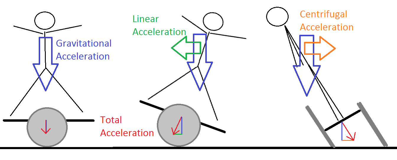
The balancing can be achieved by a combination of linear and centrifugal acceleration forces, along with gravity. From left to right: the flat board case where gravity is normal to the board requires no acceleration, tilting left or right (from the rider's view) requires a linear acceleration force, and tilting forward or backward requires a centrifugal force. The red 'total acceleration' vector in all three cases is then normal to the board.
The two main problems to solve are: what sort of response is required to the board's tilt angle, and how to determine the tilt angle in the first place.
The left/right tilt can be handled fairly easily by some statics. Allowing an additional 'drag' force (which may be wind drag or other external effects, which are significant at the speeds considered), we find an interesting result that for steady state operation the applied torque is a single-valued function of the tilt angle (regardless of the drag force). In fact, the statics tells us that the moment required to remain in steady state comes from the combination of the drag force, the linear acceleration of the vehicle, and to a smaller extent the torque exerted by the motor. Ignoring the latter gives a particularly simple expression for output torque, but this is not necessary here since the processor is powerful enough. Since the torque is proportional to current, we have a direct estimate of total motor current from the tilt angle.
The distribution of this current between the left and right motors requires consideration of the backward/forward tilt. Here, for a particular steady-state configuration, we require that the difference between speeds (rather than torques) of the motors be a particular value. This will turn the board causing a centrifugal force. In going from a flat configuration to turning, we need to make a choice on whether to speed up or slow down each of the motors to achieve this difference, and this will affect the vehicle stability. In this particular scheme, the mean velocity is used as a reference point for the velocity difference, compensated for the rider's center of mass being on a different turning radius than the board's center of mass. Thus the board is allowed to slow down or speed up during a turn and should hopefully remain stable. Now that the response to the tilt angle is better understood, we need to consider how to obtain the tilt angle.
The controller is equipped with a digital 3-axis accelerometer and gyroscope IMU (in an amazingly small package), which communicates with the processor at up to 1MHz. The IMU performs basic low-level filtering, so we are not concerned with matters like that. Instead, we want to combine the accelerometer and gyroscope outputs to get the current tilt angle with respect to gravitational acceleration (which defines the 'flat' plane). Taking into account that digital gyroscope readings require integration to get an angle, we can see that long-term use of these is problematic. However, the accelerometer is generally susceptible to short-term noise while the gyroscope is less so. Thus we combine the two outputs using a complementary filter (except in terms of vector addition, since the values of interest here are the vectors normal to the flat plane and normal to the board).
Most approaches that I have seen simply apply the complementary filter to the integrated gyroscope reading (integrated using the previous filtered value) and the accelerometer reading. However assuming that the gyroscope output is biased (that is, a zero rate of turning does not correspond to a zero output), which is the basis for the difficulty in simply integrating it, the above approach would still integrate a constant offset into the reading (it would be divided by the filter's constant though). To avoid this scenario we add a high-pass filter to the gyroscope data before combining it with the accelerometer this way. Furthermore, ideally it is desirable to put a low-pass filter on the accelerometer to avoid noise from bumps and vibration, but taking a closer look at the complementary filter we see that this is already accomplished by that statement. This combination leaves two constants (in addition to scaling, zero offsets, and dt - time between measurements, which are all assumed to be specified by the firmware), one for the high pass filter and one for the low pass/complementary filters. Adjusting those two constants requires a dataset that can be operated on, so it will be desirable to first record some measured IMU data, process it on a computer using MATLAB to find the two constants, and then supply those to the firmware. (This sort of approach will also help set up filters for the other sensors, particularly current and voltage sensing.)
While this sounds quite reasonable, we run into a few difficulties when operating in three dimensions instead of one (this problem could be 'collapsed' to two dimensions for the two tilt angles, but three is easier to visualize and computationally similar). Then what we get from the gyroscope is not simply a dtheta/dt, but a vector whose direction represents an axis of rotation and whose magnitude represents the dtheta/dt about that axis. All three (x,y,z) components are to have the required filters applied to them individually. Instead of adding the gyroscope reading to the last complementary filter value, we must rotate the last normal vector around the rotation axis given by the gyroscope. One good thing is that for small dt the associated angles will be small and thus instead of the full sin() and cos() functions we can use first or second-order approximations.
Next, the issue of self-induced IMU readings, or what I will refer to as self-acceleration, needs to be considered. By this, I mean that the vehicle is designed to operate primarily by altering its linear or radial acceleration, and whenever that happens the IMU will reflect these changes. The IMU cannot tell the difference between the board accelerating due to torque applied at the wheels and the board 'accelerating' when the rider leans backward, and our algorithm must determine this for stable control. So many algorithms miss this part that I am surprised that they even work (practically, the rider learns to counteract this)! It is possible to set up PID gains so that an unstable situation is not reached, but nonetheless any sort of physics-based tilt control will not be possible. I would venture that this is the reason many of the self-balancing vehicles I have seen do a good job of balancing but feel a bit unnatural to ride (since their control loop is always trying to make the board flat, rather than allowing the rider to actually control the tilt!). To solve this issue, the controller calculates its own acceleration from the actual measured acceleration of the wheels (based on change of motor speed) and speed of wheels. This is then subtracted from both the accelerometer and the gyroscope IMU readings by using the last measured board tilt angle as a decent approximation to existing tilt angle.
Here comes another tricky point: the calculated acceleration is in the 'absolute' reference frame where gravitational acceleration is vertical, whereas all the IMU readings are in the local coordinate frame that is based on the board's tilt angle at the time. We could simply rotate from one reference frame to another, but this will generally not be accurate since a full rotation matrix allows rotation about the gravitational acceleration vector whereas this is meaningless given the way the board is designed (only two tilt angles, but three rotation angles). The parallel transport of a vector on a sphere's surface is path-dependent, whereas we require that it be absolute. For this we use a system in which rotations about the z-axis are not allowed, where the only meaningful quantities are angle about x-axis and angle about y-axis. This makes it impossible to define acceleration vectors perpendicular to the z-axis, but this should not be a problem as all board-normal vectors are expected to be in one half of the rotation sphere. The standard representation of such a system (which I call 'irrotational' as it does not allow rotation about the z-axis) requires arccot() and cot() functions, which are computationally intensive. Here the angles involved are not necessarily small, but within +-20 degrees of zero (based on the board's physical restrictions), and by performing a few sample calculations it is seen that a third-order Taylor expansion will be sufficient.
At this point, we have a fairly robust way to extract the board's actual tilt angle from the IMU. We also have the physics basis for how that angle should translate into torque applied to the wheels. The last challenge is to put together an algorithm that will apply the necessary torque given rotor position, battery voltage, and phase currents. Work on this was cut short by a flaw during a high speed motor test. The approach taken in the firmware design can be seen in these two text files.
First the mechanism for connecting the motor to the wheels is assembled. The motor has a 10mm keyed shaft, while the 13-tooth pulley for a 5M-15 belt that transfers motion to the wheels (purchased from electricscooterparts.com) is a D bore. Since that pulley should be separately supported against belt tension instead of putting a side load on the motor shaft, I used a 'spider' shaft coupling from the keyed motor shaft onto a custom 10mm shaft that is keyed on one end and has a flat on the other end. That shaft is then supported by two bearings on either side of the pulley.
![]()
![]()
Left, the custom shaft after machining. Right, the shaft is installed onto the motor through a flexible coupling, showing the configuration that will be used in the final assembly.
The supports for the motor are second. The motor is bolted to a thin (1/8") aluminum plate which is on a set of four stand-offs to allow space for the coupling. The bearings on both sides of the pulley are press fit in an aluminum plate (getting the appropriate tolerance was difficult - on one plate I found that I milled the hole too small after taking the plate out of the vise and losing alignment; after milling it again to a larger diameter (by 0.005 in) the hole ended up oval-shaped which led to very poor bearing performance; milling out larger would however get rid of the press fit).
![]()
![]()
Left, the motor holder. Right, the supports for the wheel pulley and the supports for the bearings on either sides of the motor pulley. In the two pieces on the right of the image, note the two semicircular through-holes on either side of the bearing support edges - these are intended to allow easy removal of the bearing if necessary by pressing out on the bearing's edges rather than its center (this worked quite well in practice - ideally it requires a matching steel bar that will contact the bearing on both sides).
Third, the 80-tooth pulley is attached to the wheel (both from electricscooterparts). This is done by making one face of the pulley flat, and drilling 4 holes on it to match holes on an aluminum plate. The plate also contains 3 holes that match holes on the wheel. This is necessary because the bore of the pulley is larger than the diameter of the holes on the wheel. It also provides some space between the tire and belt edges. Ultimately, between the accuracy of the drilled holes on the pulley and the holes on the aluminum plate, the pulley was noticeably off-center on both wheels, resulting in problems maintaining constant belt tension throughout the wheel's revolution. So for future consideration, this was either a poor choice or poor machining (or both?).
![]()
![]()
Left, the pulley is made flat on one side, showing some marks of poor casting (due to its low cost, though, I am not too upset). Right, the fit of the pulley to the wheel is tested.
Fourth, belt tension needs to be considered. As the design does not include tensioners (since the belt may transmit torque in either direction) there should be a way to at least statically adjust belt tension. This is done by making the motor mount pivot such that rotating it makes the belt path longer and places a higher tension on the belt. On the motor mount plate, this requires an arc through one bolt hole centered about the other bolt hole. This may be done easily on a CNC mill, but there is another method that will probably make the machine shop instructor apprehensive (although I learned it from a machining textbook): place a tight fitting bolt with a washer and nut through the hole that is the center of the arc, place the nut in the vise, place the end mill through an already drilled hole at the start of the arc, then manually rotate the piece to make an arc. This was surprisingly less scary than I expected, and helps to provide a good intuition of the forces in milling (since usually the ballscrew of the mill table gives only a distant indication of the force at the end mill).
![]()
Milling an arc without fancy numeric control. The previously press-fit bearing is taped over to avoid metal shavings entering the bearing.
Finally the motor and wheel assembly is assembled and tested. Three issues were evident: the previously mentioned change in belt tension due to the wheel pulley being off-center made the wheel difficult to turn, the questionable machining of the press-fit bearing holes made the motor pulley difficult to turn, and a poorly matched flat on the shaft for the motor pulley allowed the pulley to slip back and forth as the flat piece was rotated towards and away from the wheel. The latter made an annoying clicking noise, while the two others made the friction of the assembly quite high. Nonetheless the motor could spin the wheel without much trouble.
![]()
![]()
Side and top views of the motor and wheel assembly, with belt.
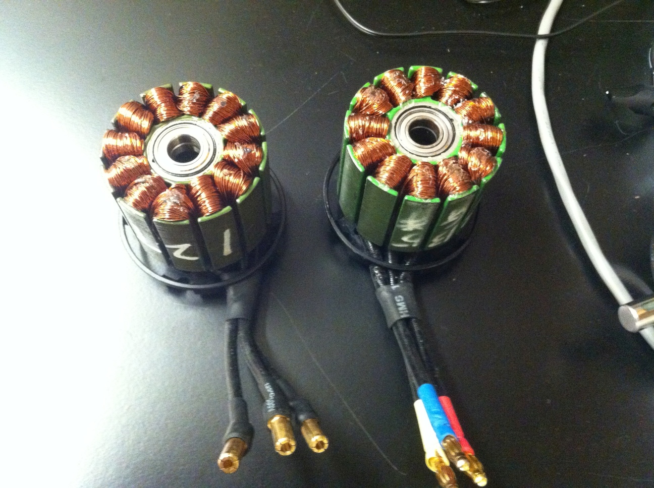
The motors I purchased were sensorless, and the intent was to add external sensors. The sensors are a TO-92 package, and need to face the motor's rotating shell at specific angles. On the inside of the rotor there are 14 magnets and 12 poles. Roughly, the poles act as 4 3-pole motors, requiring 3 phase electric power and 3 hall sensors. The sensors must be placed opposite a pole of each phase. As outlined in more detail here, the sensors are placed 17.4 degrees apart. The precise placement is ensured by laser-cutting a thin wood board with slots where the components are glued in place. The board is then rigidly attached to the motor holder with standoffs. Since I have a custom motor controller (where the rotor position calculation includes a 'sensor angle offset' parameter), there is quite a bit of flexibility in the sensor placement.
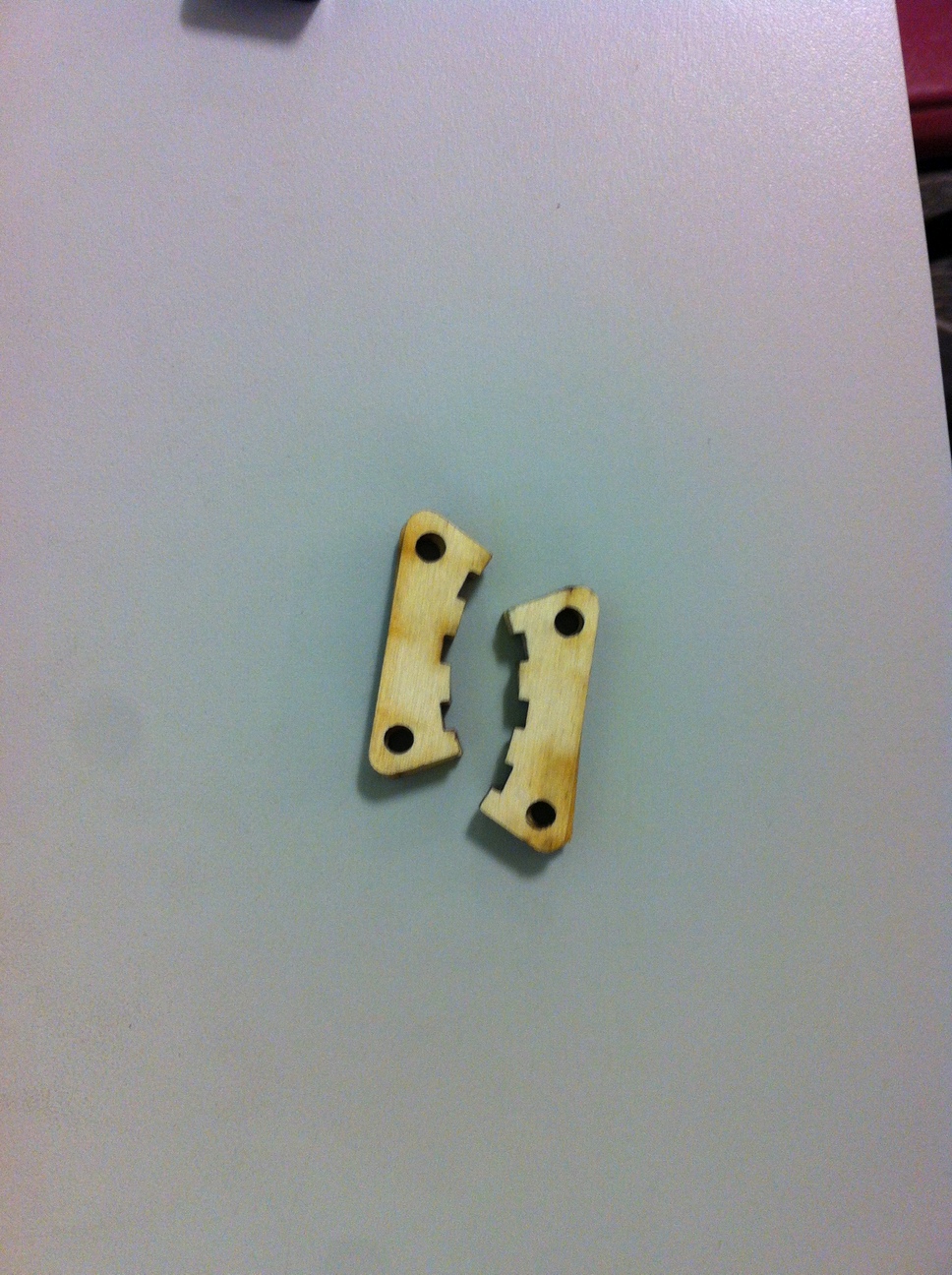
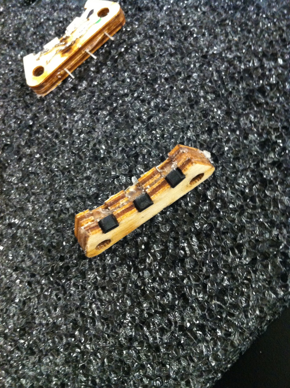
Left, the boards after cutting. Middle, the hall sensors are glued in place. Right, tiny bypass capacitors and wires are soldered on and the assembly is attached to the motor holder for the first test of the motor controller with sensor input.
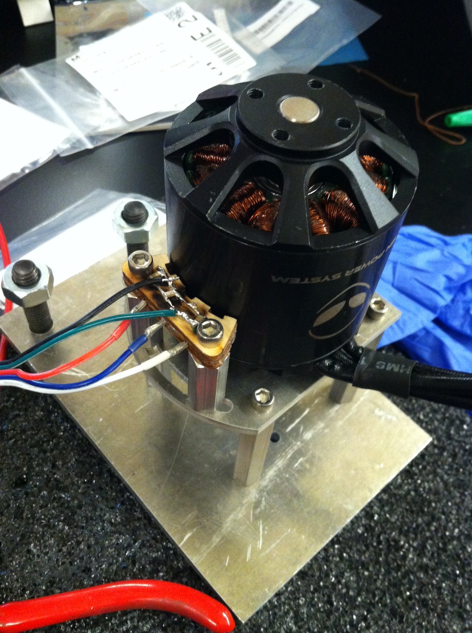
To prevent a possible unsafe condition where a magnet detaches from the outer shell of the motor, I added extra epoxy between the magnets. This is done by separating the rotor and stator by removing a retaining ring that keeps the rotor from sliding off, and then using a vise to gently push the shaft and rotor through two central bearings against the magnetic attractive force. If the magnetic force between rotor and stator is too high, it may be reduced by inserting thin steel slats to complete the magnetic circuit. For this motor it turned out to be unnecessary but is demonstrated anyways. Epoxy was also added to some loose windings, where it is important to keep in mind thermal effects and only use a thin layer.
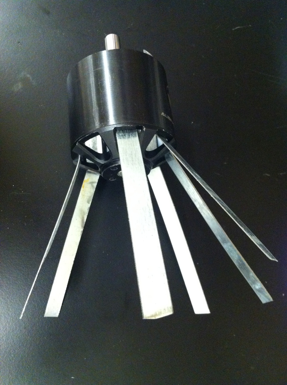
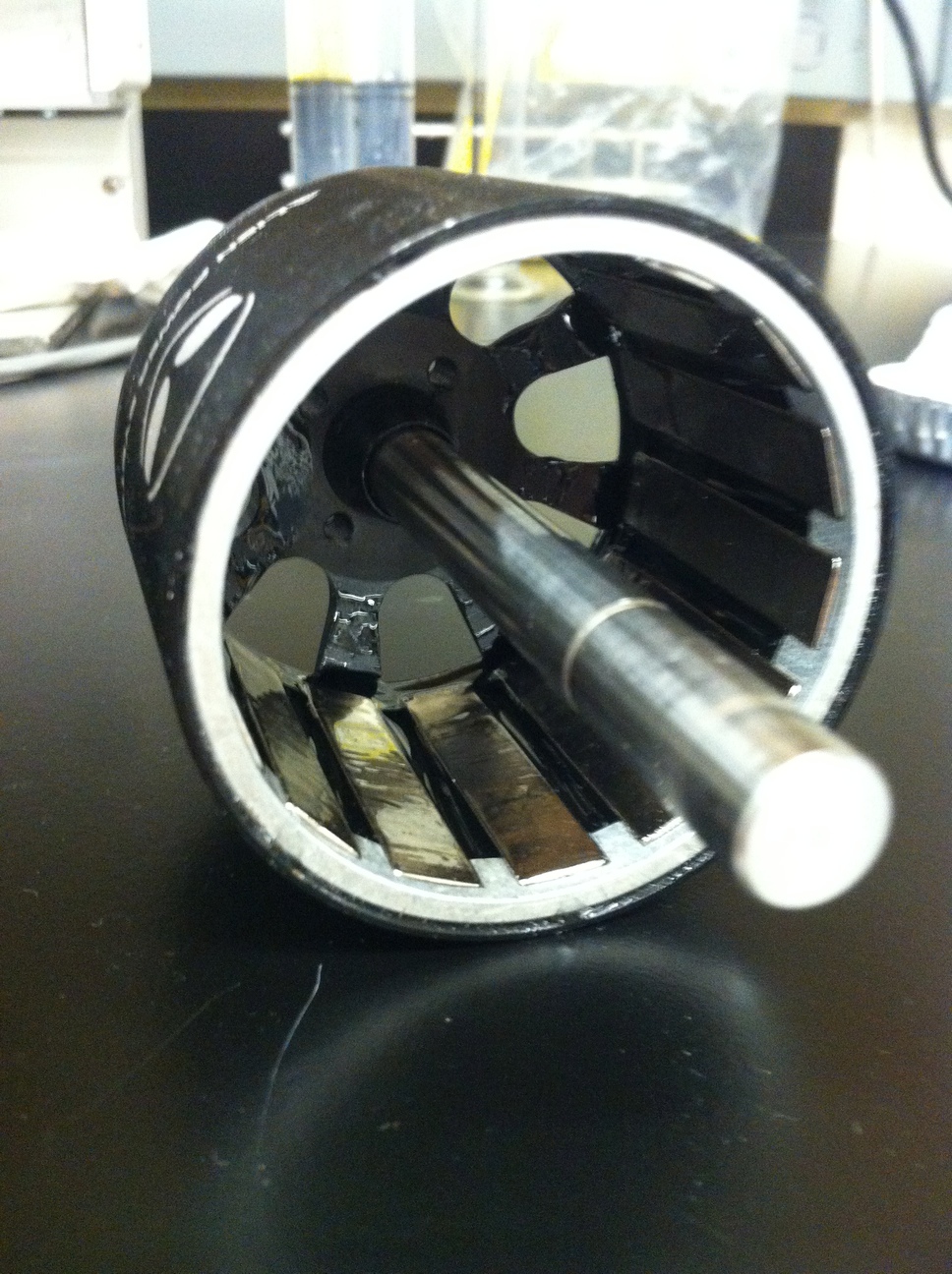
Left, slats in the gap between rotor and stator reduce the force required to separate the motor. Middle, a view of the inside of the rotor with 14 magnets. Right, a view of the stator with 12 poles and central bearings.
To improve thermal performance, I added a 3D printed 'centrifugal fan' onto the free end of the motor. Since the outside spins, this is an easy task of bolting plastic blades directly on the outside.
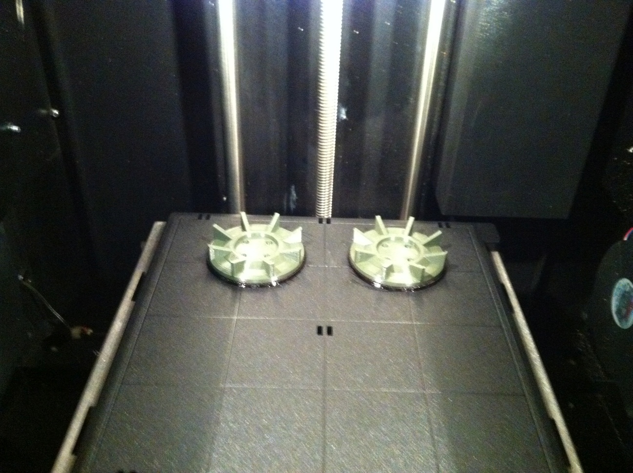
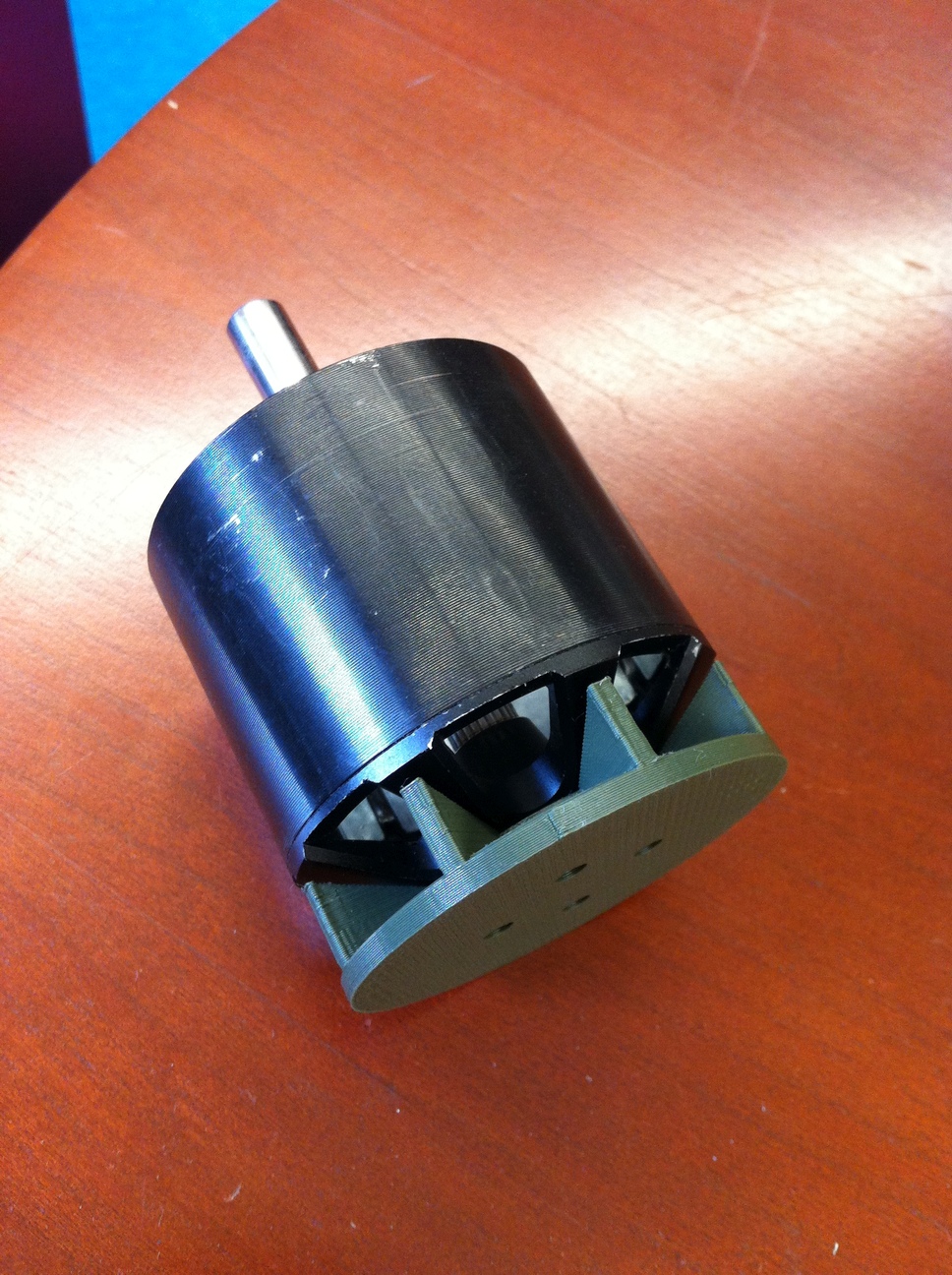
Left, plastic blades after 3D printing. Right, they are attached to the outside of the rotor to provide increased airflow when the motor is operational.
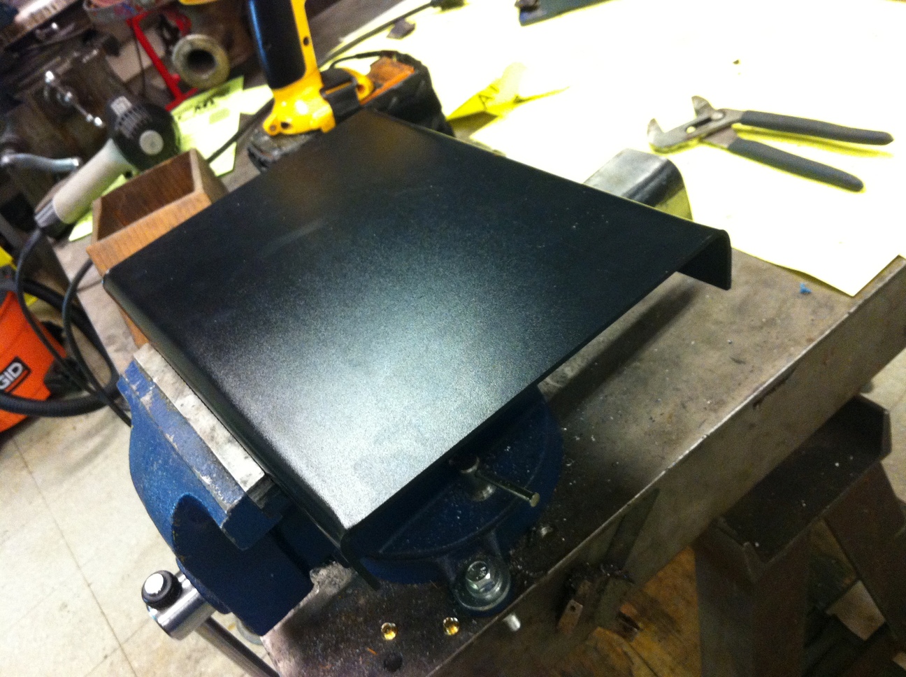
In the design of the motor controller, heatsinks need to be added to the MOSFETs in a way that the components can be air-cooled while the opposite legs of the half-bridge are isolated from each other. This required a custom heatsink design, with plastic bolts, nuts, and spacers used to ensure isolation (the plastic bolts tended to fail over time at the bolt head-thread interface, possibly due to the thermal paste, so for future designs it is better to use metal fasteners with plastic insulating sleeves). The heatsinks were cut out of a 0.031 inch thick steel sheet using a waterjet cutter. To speed up the process, four sheets were layered and bolted together prior to cutting (a similar method as used in the fabrication of stator plates for Candy).
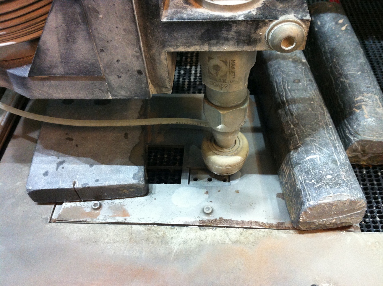
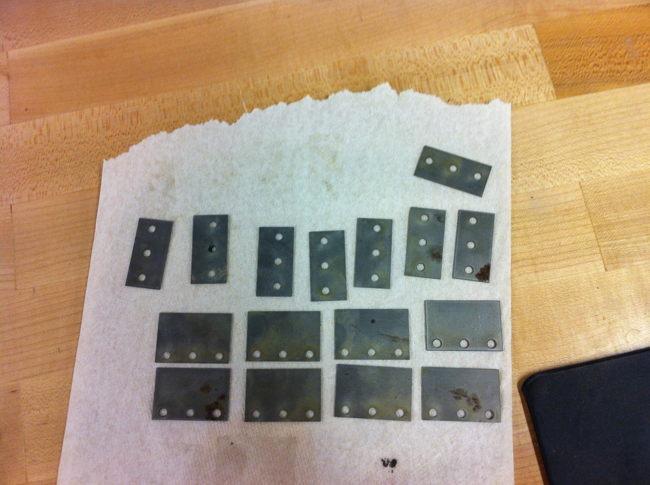
Left, layered steel sheets cut with a waterjet. Right, the finished heatsinks are separated and dried right after cutting to avoid rust formation.
Most of the frame is made of 1 inch square tubing, with 0.125 inch wall thickness. A total of 9 ft of aluminum tubing and 2 ft of steel tubing is used. Two 2ft long Al tubes under the board provide support for the rider, while a structure of 5 1ft long aluminum tubes and 2 1ft steel tubes are used to connect the board to the wheels while allowing tilt. Steel tubes are used to connect to the wheels so that a steel shaft for the wheels could be welded to the structure (I felt more comfortable welding steel rather than aluminum). The tubes are connected in a parallelogram structure using 3/8 inch steel rod, with bronze sleeve bearings for easier rotation and retaining rings to keep the rod in place. The board support tubes are connected using four 3.5 inch long 8/32 bolts (each is only 0.164 inches OD - while the steel's 170 ksi tensile strength makes this joint structurally sound, the aluminum around the bolt holes was found to yield slightly after use which was a bit of an oversight).

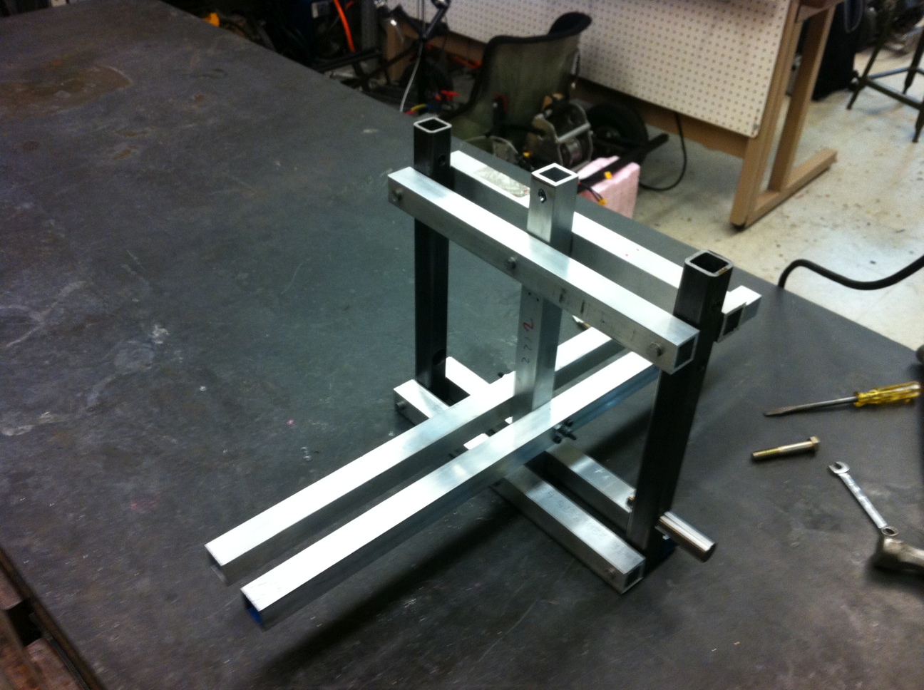
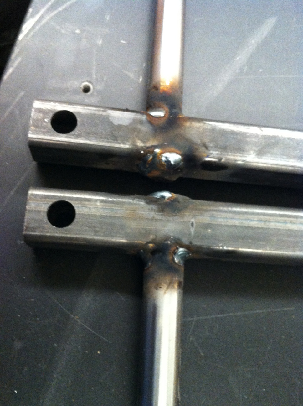
Left, aluminum tubes after marking and sawing. Middle, tubes are assembled in the 'parallelogram' configuration. Right, the shafts for the wheel are welded to the steel tubes on both sides after being inserted into a through-hole.
In order to have a decent travel range, this design uses a total of eight 5 Ah 11.1V (3S LiPo) batteries, wired as two parallel sets of four in series, to give effectively two 44.4V (12S) batteries in parallel, or 12S2P. The batteries are held in a structure under the board, for which I experimented with a thermal-formable plastic 'Kydex'. A sheet of the plastic is heated using a hot air gun and then bent manually in a vise. I think this is a good choice for simple covers and support structures, although the bend radius of the 0.125 inch thick sheet was around 0.5 inch (this could be decreased by using a sheet bending 'brake' as done with metal sheets, or by using a more concentrated heat source).
The Kydex plastic sheet is bent into shape to act as a battery holder.
At this point it is possible to test the final assembly of all the components. Another oversight is noted - the aluminum tubes forming the parallelogram structure, which have been cut square using a saw, will hit the motor holder with their edges when the board is tilted. Thus the top aluminum tubes are rounded by milling an arc around the pivot point. The change is visible in the following photos.
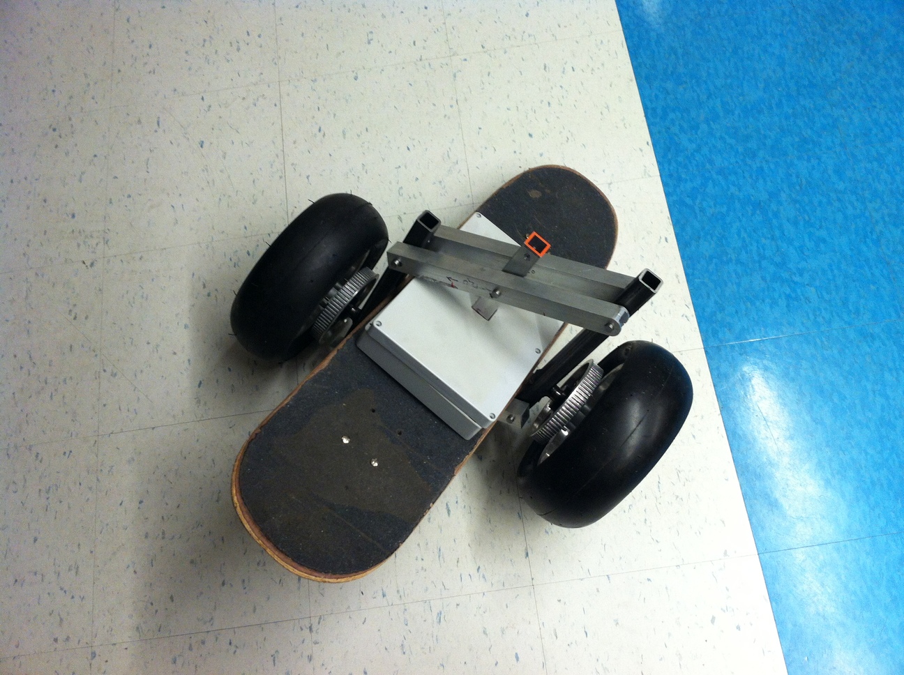
Left, the frame and board are assembled with wheels and motor controller box. Right, one of the motors is added.
One problem with the two-wheel design is that it is possible to tilt the board too far forward or backward such that the underside hits the ground. Since the batteries are mounted under the board, it is important that this is avoided. To ensure all of the parts under the board stay clear of the ground, two small scooter wheels are added to limit the maximum forward or backward tilt. The placement is calculated so that this works for all left and right tilt angles. Then holes are cut in the battery support plastic with a rotary tool and saw, and the wheels are attached to the aluminum tubes using aluminum angle stock (from the scrap pile) and 8mm steel shaft held in place by retaining rings.
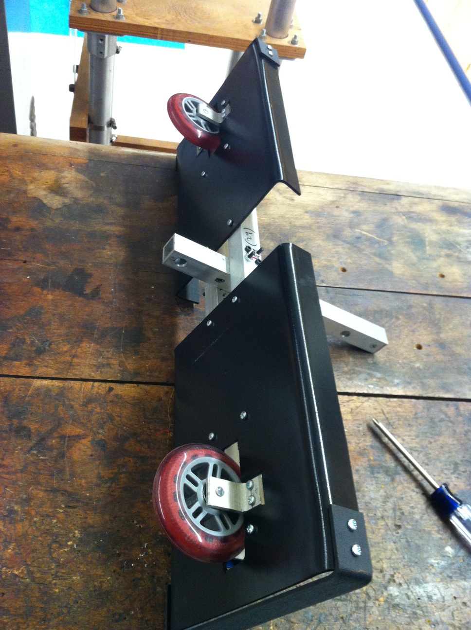
The small scooter wheels are attached under the battery holder.
Dealing with all the wires (48 for the batteries alone, and 4 meters of high current wires) was so frustrating that I barely took any photos of the process. One approach that may be of interest is how to connect multiple batteries in parallel. The easiest way (and what I recommend after dealing with all these wires) is to just buy a larger battery, but this may not be cheapest. As purchased, the batteries were eight independent units, but for this design four would need to be connected to their neighboring four. This is done by first charging/discharging each battery with a balancing LiPo charger set to a 'storage' voltage of about 3.7V per LiPo cell. Next the balancing connectors of neighboring batteries are connected to each other with a ~100 ohm resistor (ensure that the connections are made in the right order!). Assuming an initial cell-to-cell voltage difference of about 0.3V, a 100 ohm resistor will result in a safe 3mA current. The batteries are left in this configuration for a few hours to allow all parallel cells to reach the same voltage. Next the balancing connectors are wired together permanently using a custom balancing cable. This cable ensures that any small voltage differences that are reached during operation cancel out, and allows charging of the parallel batteries as a single large battery with a balancing charger.
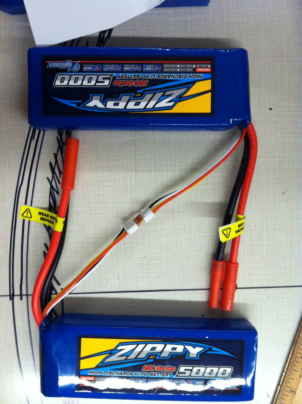
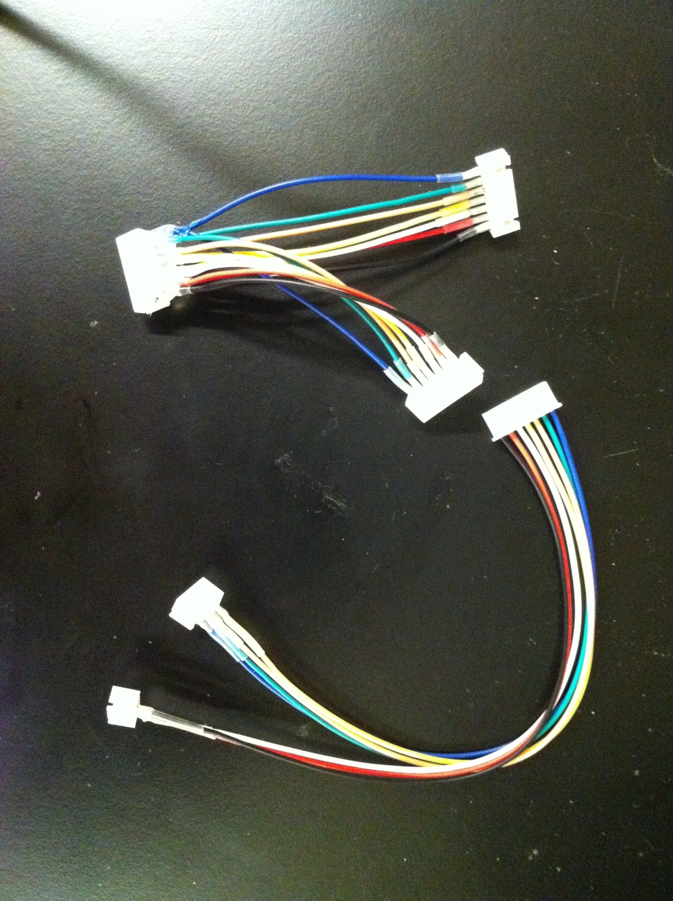
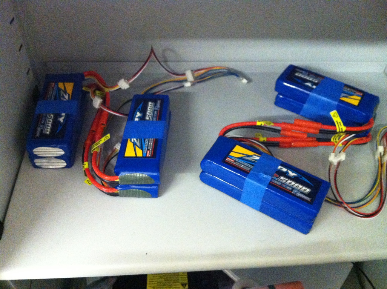
Left, the cells of two LiPo batteries are connected through resistors to ensure consistent voltages for parallel connection. Middle, the custom cables for making the larger battery are shown - the top cable connects two 6S batteries in parallel, while the bottom cable connects two 3S batteries in series as a single 6S battery; when all are connected, four 3S batteries act as a large 6S battery. Right, the batteries are connected using the custom balancing cable, and also connected in series with the high current outputs, resulting in two 6S 'assemblies' that will be in series to make one 12S battery pack.
Next the wires are put inside the structure so as to not be visible. The wires include: high current connections from batteries to motor controller, balancing connectors for batteries, key switch, temperature sensor (thermistor), varistor (to eliminate any static potential between the frame and motor controller), high current relay coil, and emergency switch. This is in addition to the previously mentioned hall sensors, motor power, proximity sensor, and LED board connectors.
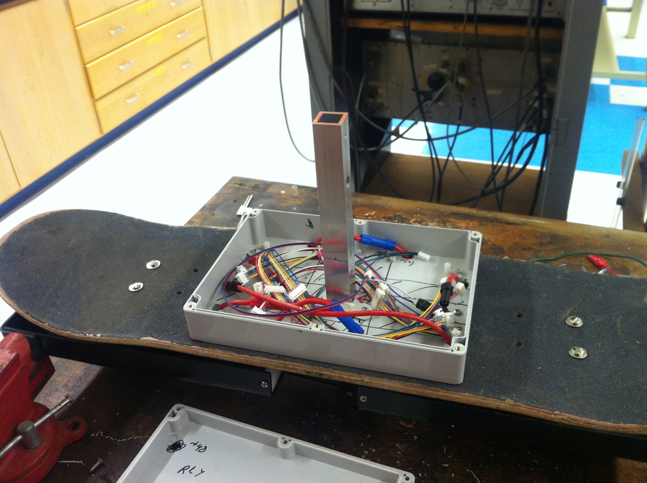
The wires are laid out inside the motor controller box.
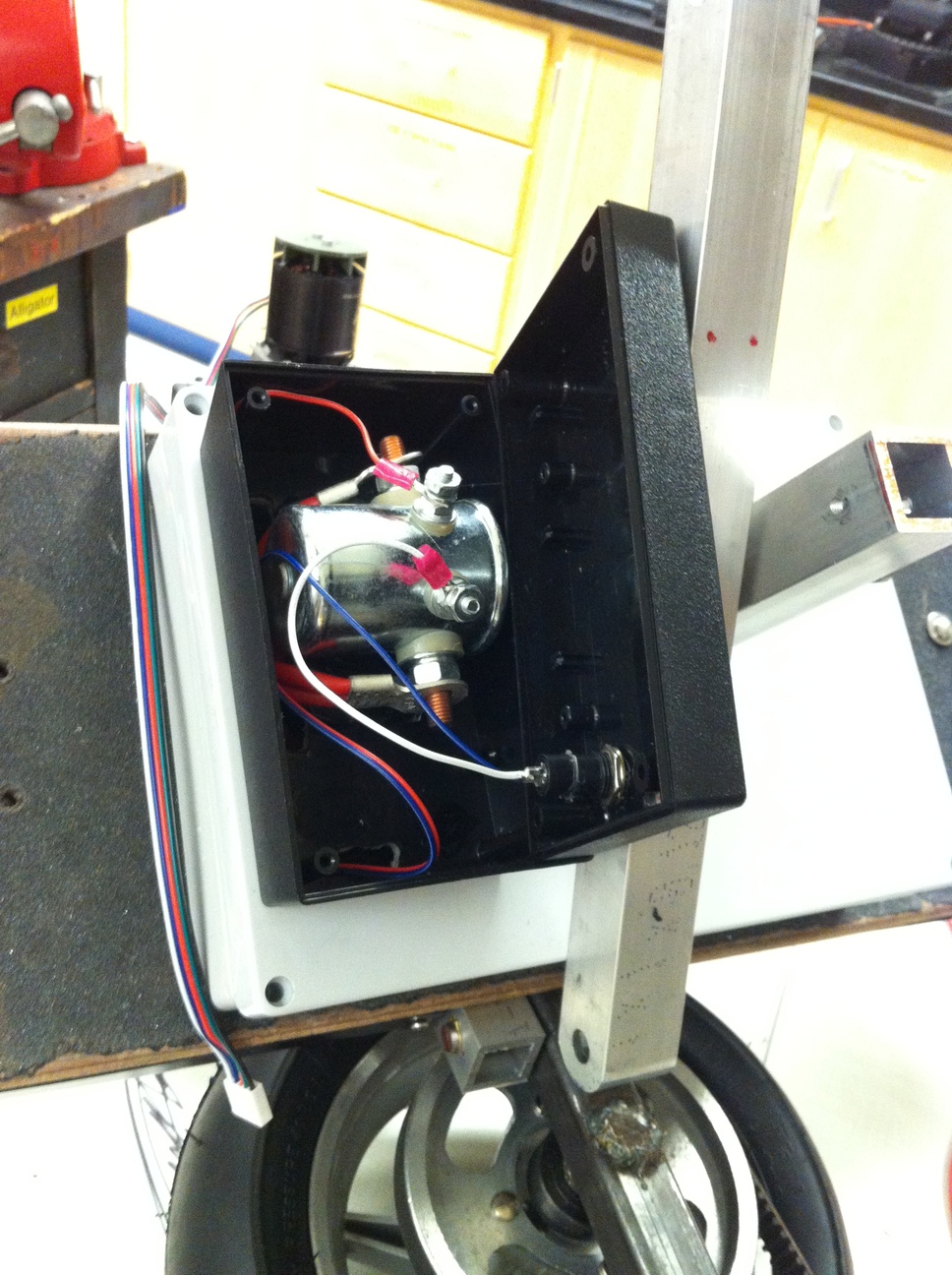
Left, the relay box is opened showing internal connections to the motor controller. Right, the outside of the relay box with the emergency off button.
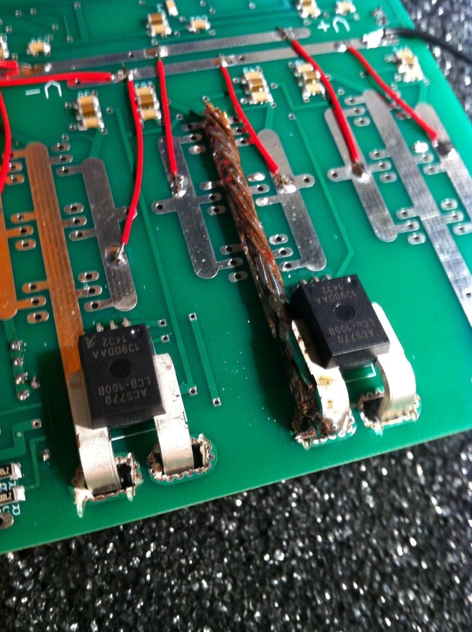
Now it is time to connect the motors and wheels to make the finished device! Unfortunately I didn't get a photo of the complete device because the motor controller broke down during a high-speed test (my guess is some problem with synchronization, likely in the code of the rotor position observer, caused the drive waveform to be 180 degrees out of phase against the fairly high mechanical inertia, destroying all the MOSFETs on the board. The gates were isolated so it was a 'safe' shutdown and the processor board survived.). I was so disappointed that I didn't take any more photos.


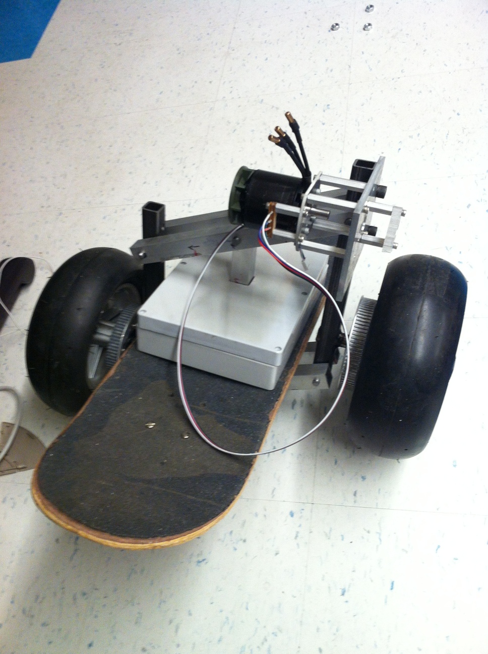
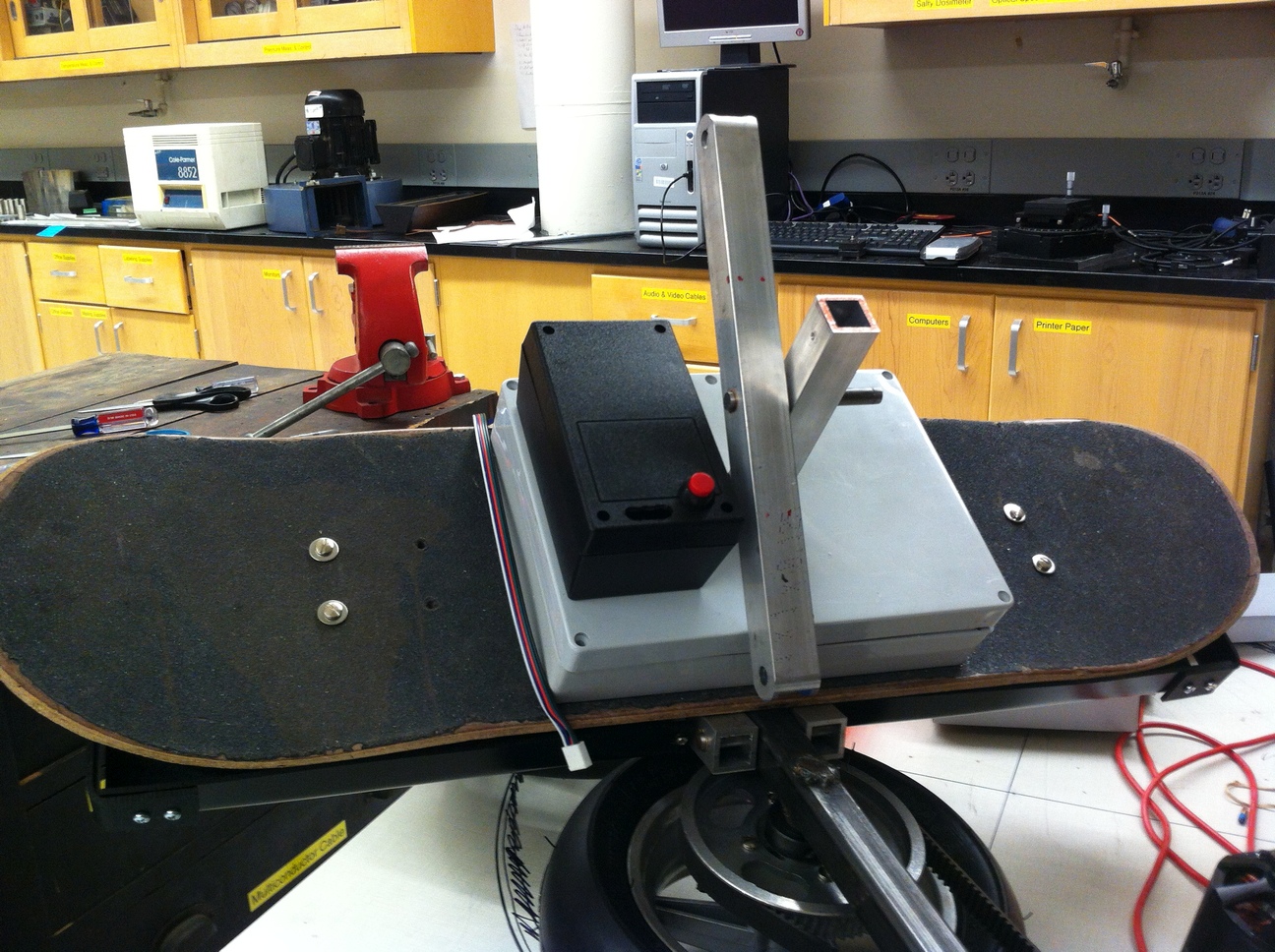
Two views of the almost-finished hoverboard. This is before the above relay box was installed, it would be on the opposite side of the motors here. However all other components are in place, including a key switch at the top of the central vertical tube.
For others interested in making a four quadrant FOC brushless motor controller, I would strongly recommend adding a high resolution rotor angle sensor, as opposed to the approach I attempted of estimating rotor position from the hall effect sensors. There are some nice sensors that require only a single magnet on one end of a shaft, and the sensor tracks the changing direction of the magnetic field (like a compass) as the shaft rotates. Other approaches like optical encoders are also possible. The hall effect sensors give 6 unique outputs per single electrical revolution, so for a 14-magnet rotor this means 6*(14/2)=42 'counts' per mechanical revolution. Any sensor that improves on that number will be a great help. Additionally, the F28335 as well as other processors have dedicated hardware to interface directly with a pulse based encoder device, but require custom programming to process hall effect sensor data in a way that is useful to an FOC code. The simpler (but more noisy) approach is to use block commutation if hall effect sensors are the most convenient.