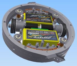
The CAD model of Candy (made with Autodesk Inventor).
During my experience with designing and building a 30lb ring spinner (Cathi) as part of RoboJackets, I enjoyed the design too much to have its fiery defeat in a match be its last expression. So this year, for Motorama 2015 (Feb 20) I am building a 3lb ring spinner, now on my own time and budget since I have moved up north. This has led to significantly more design freedom and, not being able to resist, I took pretty much all the chances that I was able to in this design. Will it explode? Implode? Spin up and destroy itself? Or perhaps actually work? We'll see in February.
The main flaw in Cathi was the weapon drive. Unsurprisingly, with a ring held only by its inside part it is quite difficult to transfer a torque. The approach in Cathi was a friction drive, which pressed the belt between a roller inside the ring and the inner surface of the ring. The belt was also wrapped around an outrunner motor which acted as a second pulley. This worked well enough during the trials but sudden acceleration/deceleration easily ripped the belt and made the weapon useless. Also because of the roller and pulley design, sometimes the friction between the belt and ring would be rather low leading to poor power transfer between the motor and ring. Overall a messy design that should have been avoided. Instead, Candy uses magnetic fields to spin up the ring. That's right, the ring itself will be a rotor of a large split-stator induction motor with the rest of the robot as the stator. Originally a switched reluctance motor was chosen (due to low weight because there are many airgaps) but its high VA requirements and difficulty in controlling (requiring position feedback) led to use of induction concept (no need for position feedback, lower VA, but higher weight).
Another weapon drive flaw was the bearing system. Cathi used machined one-piece pulleys to hold the weapon, which removed the possibility of adjustment and led to either very loose or very tight weapon movement. For the fast RPMs desired in Candy, this would be unacceptable. Instead, Candy will use two split pulley-like pieces (I call them collars) each of which can be adjusted to move the weapon up/down as well as move the contact point in/out. Proper adjustment of these, with 0.005 inch shims, should lead to very smooth weapon movement, highlighted by the no-idle-torque of the induction motor (opposed to permanent magnet motors which tend to lock in positions of highest flux linkage). In addition, the contact angle between the ring and bearings was low (close to horizontal) on Cathi, which was changed to high (close to vertical) on Candy in order to decrease rubbing (shear) friction between one edge of the bearing and the other.
The next flaw was in the drive system. The brushed motors used in Cathi were vastly overvolted, and burned out during the competition. Other 3lb bots during the competition had problems with brushed motor controllers. Also brushed motors have brushes which are messy and can fail. So the approach in Candy is to use brushless drive motors, properly rated and with brushless racecar controllers (allowing reversing) from HobbyKing which are cheap and reliable. The brushless motors are very fast, requiring a gearbox, and an easily accessible one was used from a regular cheap brushed gearmotor. The wheels were kept near the center of gravity and were made with soft rubber for traction.
The final significant flaw was in the weight. Going by estimated weights in Inventor CAD program, the weight estimate for Cathi was off by 3lb or 10%. This led to undesirable reduction of weapon weight. This would be unacceptable for Candy, since reduction of weapon weight would significantly undermine its strength. Thus in Candy design, every component was precisely weighed as soon as it was available (including bulk metal), in order to obtain the most accurate weight estimates. Additionally, the inside will be built and weighed before the weapon is finalized, allowing for changes before machining in order to perfectly meet the weight requirement.

The CAD model of Candy (made with Autodesk Inventor).
The starting design parameter was weapon energy. After watching Dominant Mode blast other bots, I thought that perhaps if I can dump sufficient energy into the ring I can achieve similar effects. Thus the ring is designed to hold about 1 kJ kinetic energy when spun up to its rated speed of 10000 rpm. Who knows whether it will actually get there (if I will be brave enough to stick around when it does). Even at 500 J it should do some decent damage, and that is only 7070 rpm.
Next was the profile. One advantage of a ring spinner is its low profile, since there are no protruding weapon spinning bits and it is fully invertible. I decided, based on the height of an available gearbox for wheel drive, that the inside height would be 1 inch. With outside plates and bolts, the total height is about 1.2 inches, which is quite low in the battlebots world. This makes Candy an effective 'undercutter', being able to sneak under taller weapons to munch on corners and supports. The outside diameter is also quite low, about 7 inches, making Candy a very compact robot. This was done because any increase in diameter under a constant weight constraint significantly reduces the rigidity of the weapon structure since it has to be made thinner and flatter.
I expected the custom designed weapon motor to be fairly inefficient, so decided to simply dump enough power into it so that's not a problem. For this I employed two batteries, one 2S 1300mAh for electronics and drive, and another 4S 1000mAh wired in series (for 6S total) for the weapon drive. The weapon will be able to receive a peak of 24V * 20A = 960W, for a 2-second spin up assuming efficiency of 50%. Of course having this much battery power added a bit of weight, but it was not too unreasonable and the batteries chosen fit into the robot internal dimensions (a 4S 800mAh would have been better electrically but strangely did not fit). The only potential problem here is if the 2S discharges before the 4S does, since they are in series it will be forced with a negative voltage and could catch on fire. So at least one more way for this to end in flames! I won't feel much satisfaction from knowing this if it comes true, but at least you can't say I am not aware of the risk. One has to make sacrifices at some point. Perhaps I will set the speed controller to shut everything down when the 2S voltage falls to a critical level.
The placement of all the parts in the robot was a bit of a pain, having a detailed CAD model (complete with photos and weights of actual components!) helped. In the end I made the profile even smaller, a bit under 6 inches for the internal part. This allows more material to be used in the weapon construction.
I started machining with the wheel motor attachment structures, made out of some scrap aluminum. The piece turned out to be more complicated than I initially thought (machining from three sides, also tapping blind holes), I had not used a mill in at least 6 months, and I was in a brand new shop so the first try turned out not quite as expected. A few hours of re-learning later, I had two quite usable motor mounts. As usual, I like to make the holes as small as possible, which is great for rigid structures but terrible when the dimensions are slightly off. In this case they were slightly off, causing pressure in the gearbox and making the gears jam somehow. Everything else came out fine, and I was pleasantly surprised by how much machining I remembered from the RoboJackets builds.
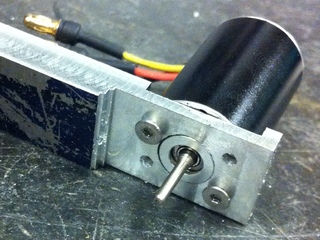
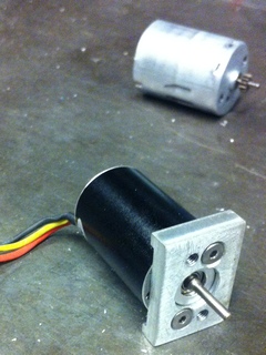
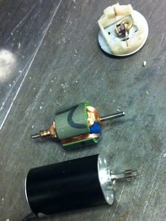
Motor mount during machining, motor mount after machining (before adding holes on top/bottom), and comparison of brushless motor (bottom) and brushed motor stator/brushes (top).
I was hesitant to make the wheels because of some bad experiences with the lathe. Last year on RoboJackets the lathe toolkit was decidedly lacking, and most lathing was of steel, tool steel, and huge aluminum blocks. Lathing in that build season was a grueling process that usually resulted in botched pieces. Then a CNC lathe arrived, and I decided to test my prowess which activated some feature that spun up the chuck to a few thousand rpm and set the carriage on auto-feed going straight into the chuck (and fast!). Who would know that 'Feed hold' does not work anymore when you set the lathe to do threading? After mashing that button, and then all the ones nearby, I came upon the Emergency Stop barely in time to avoid utter disaster. Now I tell others to try pressing the Emergency Stop button when teaching how to use a machine.
In the new shop it was quite different, first because they had an assortment of nice and sharp lathe tools readily available, and second because I was cutting plastic and felt no worries about breaking those nice tools. Third, because these were wheels and only the center hole had to be precise in any sense. So I went about lathing the plastic rod into wheel-like objects and it turned out to be quite enjoyable. The wheels also came out OK!
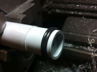
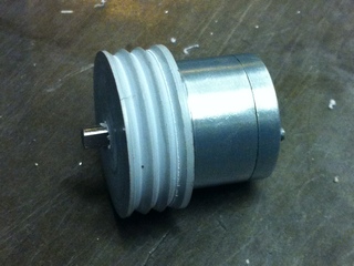
Machining the outside surface grooves and central hole for Candy wheels on the lathe, wheel fits on the motor gearbox (shown here without traction O-rings).
The rest of the robot is essentially waterjet parts and purchased parts (standoffs, bolts). The remaining significant work is on the weapon ring (lathing, drilling) and weapon teeth (countersink, harden).
Waterjetting the top/bottom aluminum plates went without much problems. I decided to undersize the through-holes in the CAD in order to have a tight fit by re-drilling them with a properly sized drill (which would leave a better finish than the waterjet for a hole), so all the holes were about 0.005 inches too small to fit the bolts. The only problem was that I could not find a properly fitting drill bit, so ended up using a tiny round file to widen the holes until the bolts fit - would not recommend doing this again. Luckily I realized that this would not be a good approach for the thin (0.01") steel laminations, so the holes were sized exactly to match the bolts as measured by calipers (this is slightly tighter than the standard 'close' tolerance for through holes, which can lead to problems in alignment but is better for holding small parts in place). The resulting pieces fit without a problem, but successfully pulling this off requires calibrating the waterjet nozzle offset before cutting as described below.
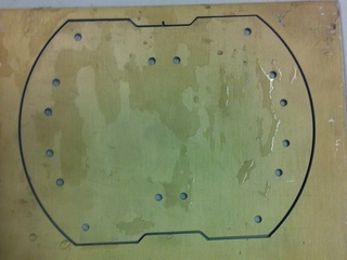
The base is cut out from a sheet of anodized aluminum using a waterjet.
The steel for the weapon motor stator was bought as shim stock, a 6x100 inch roll of low-carbon steel of 0.01 inch thickness. The waterjet is better suited for cutting parts in the 0.125-0.25 inch thickness range, so the roll was cut into 11 6x9 inch sheets, which were then flattened and stacked in alternating orientations to ensure the final piece did not retain a net bend from the initial roll shape. This assembly was aligned along two edges and then drilled and bolted together around the perimeter. The bolted assembly of 11 sheets (0.11") is then ready for the waterjet.
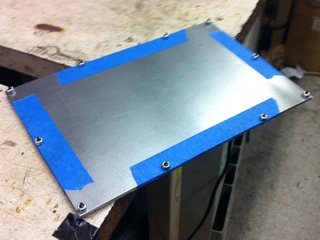
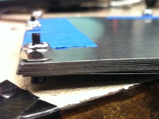
Steel shim stock is cut into 11 sheets and they are bolted together along the edges. A side view clearly shows the resulting layers.
For this part it was important to use tabs to prevent the cut pieces from falling into the waterjet or floating into the cutting head. The cut itself was quite successful, after a slight adjustment of the tool offset to ensure the piece dimensions were correct (a source of endless tolerance problems at the GT waterjet until I learned about this feature!). The tool offset determines how far away the cutting stream is from the outer edge of the part as specified in the CAD model, and clearly if this distance does not match the actual diameter of the stream the part will come out too large or too small. Thus for high precision parts (0.001") I would recommend starting with a test cut and comparing the size of the cut piece to the size of its model - if the two do not match, the tool offset needs to be changed (it is applied around the perimeter so if a rectangle is longer than desired by 0.01 inch, the tool offset should be decreased by 0.005 inch).
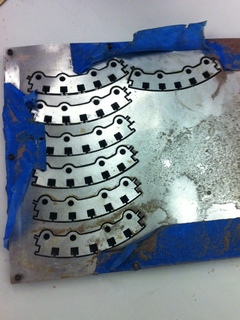
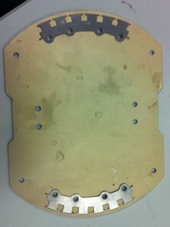
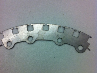
77 stator patterns are cut in the stacked steel on the waterjet, the bolt holes line up with the base, and a close view of one stator lamination showing the two tabs on the sides used to keep it in place.
As I realized after the fact, cutting layers of steel as done for the stator leaves a tremendous amount of exposed surface area that enables corrosion to occur, especially since water from the jet gets trapped between the layers. The way to remedy this would be to take apart and dry all the layers immediately after finishing the waterjet operation. However, I left the metal out for a few hours after cutting, and the results were not too pretty.
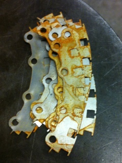
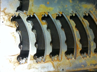
All of the stator pieces are rusted, along with the sheets they were cut from!
While this is not a terrible setback, and might even have some benefits in that the rust surface is less conductive than the metal (the stator is designed to be non-conducting to avoid eddy current losses), it just looked bad and led to a nonuniform thickness profile that would be problematic when it came time to stack many of these parts to make the stator. To remedy this, I ended up sanding both sides of each steel piece, a rather tedious process because there was no good way of holding the pieces in place. After finishing about 5 pieces by sanding on a surface and holding the piece in hand trying to avoid touching the sandpaper (with 72 more pieces to go), I was anxious to find a method to better hold the piece while sanding. Luckily the magnets for the motor already arrived, so I attached a few of them to a steel bar and placed tape over them, which ended up holding individual rotor laminations quite well during the sanding process. This made the task significantly easier and I was able to finish in a bit over an hour. It really is better to separate and dry the metal immediately!
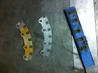
Before and after sanding the rusted stator laminations, with the magnetic tool used to hold them shown on the right.
At this point, I could not resist putting together the pieces that I had, since this included most of the internals of the robot. There was also a practical reason to do this - as mentioned before, I was strictly controlling the weight of the robot, and knowing the actual weight of the half-built robot would help me revise the CAD model for the rest of the robot (essentially just the weapon), and change the design of unbuilt parts to stay within the 3 pound weight limit.
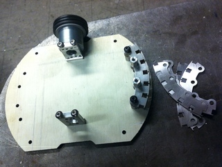
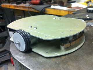
Testing the fitting of the recently machined parts is successful!
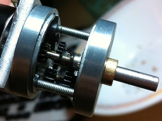
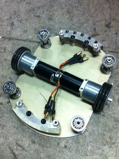
Cutaway view of the brushed motor gearbox coupled to the brushless motor (the gear was transferred from the brushed motor to the brushless), and another test fit with the drive motors in place.
The precision bearings used for the weapon motor did not fit on the steel standoffs bought for them, so I spun the standoffs in a hand drill against sandpaper in short intervals until the bearings could just barely slide on with a press fit - I would recommend a similar method (sanding slightly oversized pieces) for precise and tight connections. With the bearings, stator, and drive motors attached, the robot came in under its expected weight, which is always a great find (I used some conservative estimates for unknown/uncertain part weights, and hobbyking parts in particular are definitely uncertain). This allowed for the expansion of the weapon's outer diameter from 6.4 to 6.6 inches (inner diameter 5.7) to bring up the expected final weight by about 0.1 lb to 2.99 lb, which already includes allowances for wires, all bolts, stator winding, epoxy, etc.
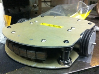
Final test fit with stator and weapon bearings.
With the model re-adjusted for the proper weight, it was time to waterjet the weapon elements. The weapon consists of three stacker layers of 0.375" aluminum, for a total height of 1.125" which matches that of the outside surfaces of the top/bottom panels (but not the attached bolts). Ideally the weapon would be a single block of aluminum, but doing it this way is significantly cheaper and easier to machine. The split was done in three sections because magnets (also 0.375" tall) will reside in the central section, and the outer sections should be a single structure for a properly machined fit between the weapon and its bearings. In the initial design, the plan was to have a steel middle section, but this proved to be excessive weight, where making a thicker aluminum structure was better than a thin aluminum-steel structure; however at this point I already purchased two aluminum sheets so I could not machine three individual rings to stack. Instead, I used the two sheets for the precision-surface top and bottom rings, and made some arc sections from the 'inside' material of the two rings, thus reducing wasted material and still effectively getting three rings. The only problem to consider is the resulting loading in the weapon, since the arcs will necessarily experience centrifugal force but will not be able to counter it without external support. My plan was to get around this by welding the weapon structure together (as well as bolting it), and for this reason quarter-circle cutouts were made in the corners of the arc pieces (this would accept the welding fill material and allow for increased bonded surface area). This ended up not working too well (it was difficult to heat up the curved area properly), I would recommend just having a regular flat surface to join the pieces.
The waterjetting of the weapon structure turned out to be problematic. The waterjet did not cut through the aluminum on the 0.375" thickness setting, which led me to change the setting to 0.4", and the waterjet still did not have an effect. After some further testing, it was found that the hose supplying abrasive to the nozzle was somehow clogged, so essentially only water was made to cut the metal. Remedying this problem allowed the cut to finish, but the cut quality was very poor, with many pits/bumps/tapered edges from the water-cutting action of prior passes. Hopefully these pits will not serve as crack initiation sites during a match, and hopefully welding the structure will help further. Ideally, this problem should have been fixed much earlier - for this I would suggest visually checking that abrasive is flowing while the machine is cutting. Also if a part comes out with poor cut quality or is stuck from the cut not going all the way through this is a sign of some blockage in the abrasive flow. If water streams from the nozzle in the direction opposite to where the nozzle is traveling (ie back along the cut path) this is a sign that the hole was not made all the way through the material and material in the cut path will have noticeable water flow ridges/pits. Also, upon piercing (starting the cut), if metallic/gray dust rises from the pierce area (as opposed to orange/brown with abrasive present) this is a sign that the pierce is occurring without abrasive, usually a bad scenario.
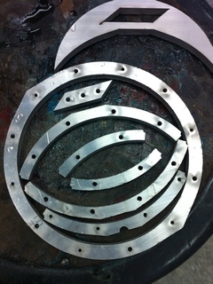
Pieces of the weapon ring on the waterjet - the middle section that is split into 4 pieces was cut out from the metal in the center of the continuous outside rings, to use the aluminum stock effectively.
Even though the bolt holes on the weapon were properly sized, the waterjet trouble led to the necessity to again use a tiny round file to widen and straighten irregularly shaped holes. Then, the holes were tapped and countersunk to enable the assembly of the aluminum part of the weapon. The countersink was done in a two-step method: first, a drill bit of the desired diameter was used on a drill press to start the countersink hole (note the drill bit ends in an angle, so it cannot be driven as deep as the desired countersink depth, and here it is adequate to drive it in only enough to have the hole radius+location established in the metal). Second, an end mill of the same or similar diameter as the drill bit is used in the drill press (on lower RPM) and the presence of proper diameter holes makes it easy to center the end mill even without supporting or clamping structures. The end mill is driven to the desired countersink depth.
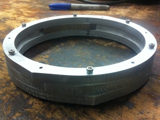
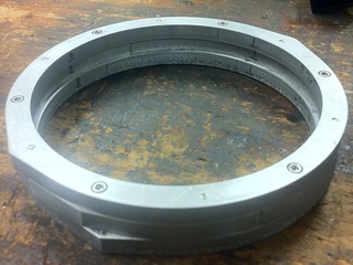
Ring weapon before and after countersinking, a row of test magnets is visible in the back internal surface of the ring.
The edges and sides of the aluminum pieces were sanded for better appearance, and where necessary filed to remove artifacts from the waterjet problem. After that, and widening a few more holes to get the assembly to fit, the weapon could be assembled, with a total of 12 bolts and 6 aluminum pieces. The fit of the magnets inside this structure was tested, and they seemed to fit OK, even if requiring a bit of a press fit (this turned out to be an issue later on, there should have been more internal clearance between the top and bottom rings).

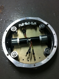
Ring attached to the robot frame to test fitting (bolts not used), view with top plate on and off.
Next the entire assembly was spun on the lathe to get the rolling surface for the bearings smooth. The design requires an internal surface of the ring that is tapered at a precise angle that matches the angle of 'collars' on the bearings, and also that is centered about the same axis for both the top and bottom parts of the ring. This is very difficult to achieve unless essentially the same setup is used for all operations. In this case, I set the taper angle on the lathe to approximately 20 degrees as called for in the design, then kept that angle while machining both sides of the weapon ring and all associated bearing collars. Additionally, when flipping the ring, a gauge was used to center the ring such that the second cut surface would not be off-axis with respect to the first one. The operation probably took around 6 hours, with the bearing collars being probably the most annoying pieces to machine (because they require 3 fairly precise surfaces, leaving nothing to hold them by while machining! Also the thin aluminum sections get bent easily even by regular lathe operations). This was so exhausting I didn't even take any photos of the process.
Quite a bit of problems came from trying to fit the magnets inside the ring. I used a steel strip behind the magnets to complete the magnetic circuit, meaning that first the steel needed to be epoxied to the aluminum, and then the magnets epoxied to the steel. Cutting the strip out of a large sheet of steel caused significant curvature in the strip, and this did not go away when it was epoxied inside the ring, making it necessary to grind excess steel to have a somewhat uniform inner diameter. Even then, after arranging the magnets it was evident that some were sticking out too far and would rub against the stator since the airgap is only about 0.01". Once again the requirement for a precision surface with a 6-inch diameter was not in my favor.
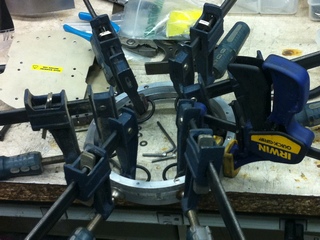
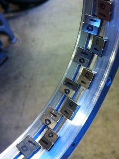
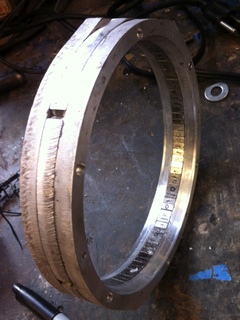
Epoxying the steel strip to the aluminum ring required clamping all along the inner surface of the ring to ensure the steel strip would be flush against the aluminum (it still wasn't). Magnets were laid out in a 2-magnet per pole configuration, which was easiest to do by splitting them into 'dipoles' like NS and SN which are stable individually, then bringing two together to form NSSN. The magnets were attracted to the steel and did not require any external pressure in the gluing process.
Next it was time to put together the stator. A few thin layers of polyurethane coating were applied to each side of each steel piece, but nonetheless there was some conductivity measured between them (not necessarily a problem - as long as there are no loops it is ok). Then 35 sheets were stacked to form each stator, bolted together, and kapton tape used to cover possibly sharp edges so the windings would be less likely to short.
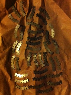
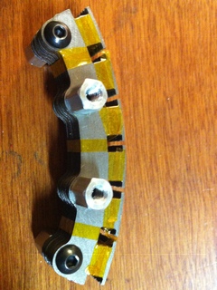
Stator pieces laid out on paper to spray polyurethane coating, then are stacked into a complete stator and taped.
Finally the teeth were made from steel bar stock, by cutting the stock at an angle. A prototype tooth was cut on the waterjet out of aluminum when making the ring, which helped to machine the teeth without the need for precise alignment. Nonetheless it was found necessary to use a mill to transfer holes from the aluminum to steel tooth, and to countersink these holes. After two teeth were machined, the holes were transferred to the aluminum disc, then the teeth attached and ground down as necessary for the entire weapon to fit in the desired 1-in height profile. Then, knowing that the teeth would fit properly, they were hardened by heating to 1500 F for about 30 minutes and then quenched only along the long sides - ideally this would lead to a hard 'hitting edge' while maintaining more ductility in the bulk of the tooth where it attaches to the bolt and has to absorb the impact of the hit.
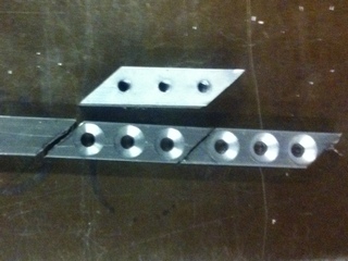
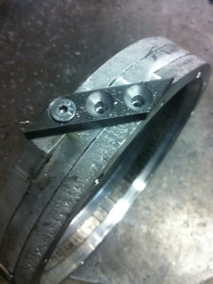

The weapon tooth (W1 steel) is cut, then fit to the ring, then heat treated.
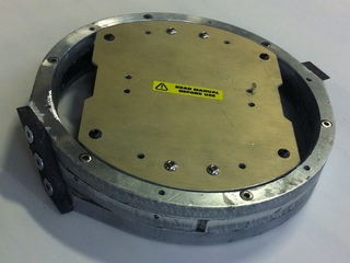
The ring weapon is completed and placed on the robot.
The robot contains two batteries, a radio receiver, and three motor controllers, as well as two brushless DC (BLDC) geared motors for the traction drive, and one switched reluctance motor (SRM) for the weapon drive. The BLDC motors are controlled using two racecar ESCs from HobbyKing, since they allow reversing and are very light. The SRM is controlled by a Plush 40A ESC, modified for SRM drive circuit and with rotor position sensors added.
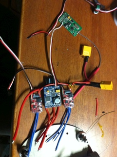
The electronic components are soldered together.
The problem once again was getting everything to fit inside the robot. The CAD model left no room for any extra components or even wires overlapping. In fact the Plush 40a controller used was too large to fit, and my plan was to remove circuit parts to get it to fit. This controller has a massive 5A BEC, and an associated huge inductor and capacitor for the buck converter, and these were removed with the 5V for logic provided by the more appropriately sized BECs on the wheel ESCs. This worked successfully without further board modifications - the board did not have a protective diode or other features that would make this difficult.
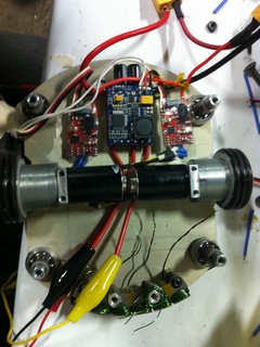
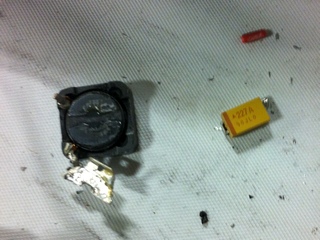
The electronics are placed in the robot, and then the inductor and capacitor are removed from the large 40a controller, these were the biggest components on the board, and removing them reduced the thickness by more than 1mm!
The stator was then wound, in a delta configuration, with the pattern AaBbCc (it is made to look like a standard 12/14 brushless motor, which is equivalent to 6/7 on each stator, meaning 7 magnetic poles fit in the space of 6 poles on the stator). (Note the actual scheme for dLRK winding is AabBCc, this is probably one reason the motor did not work. I will update this after rewiring...) The magnetic flux loop is then a short path through two nearby windings and associated permanent magnets, rather than through any long section of the ring or stator. In essence this is a linear brushless motor, or an 'unwrapped' traditional motor, split into two halves. There are 96 individual magnets on the ring, which corresponds to 48 poles, of which at any time 7 will be facing each stator.
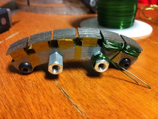
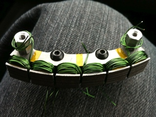
One phase of the motor takes two consecutive poles, one wound clockwise and the other counter-clockwise, so that a current flowing through the phase will create a magnetic flux loop going through these two poles. The six poles are then wound with three phases total.
The stators are connected in series, with reversed orientation (so that both provide torque in the same direction), and then at one end the three phases are joined together in an internal connection as typical of a delta configuration.
Then all that is left is adding the batteries and putting on the cover! (What about a power switch? Oops..)
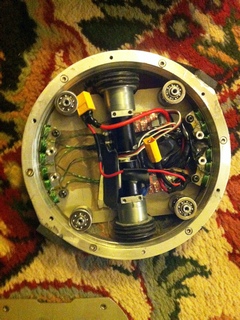
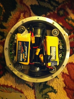
Electronics before and after adding batteries such that everything fits inside the robot and doesn't touch the destructive sharp spinny parts!

It actually is possible to put the top plate on with all electronics inside, the LiPo batteries just have to be squeezed a little.
It didn't work at all! The airgap turned out to be too small, and the magnets stuck to the stator steel with tremendous force. Attempring to separate them and spinning the disc resulted in 'clicking' or cogging torque as seen in working brushless motors, so maybe there is still hope? In any case, I will detail some shortcomings of this design to avoid them in the future: