When flying home from Atlanta one day, I brought along the previous version of the LED strobe light. The TSA considered the flashlight a dangerous terrorist weapon and promptly confiscated it. Since then I've stopped taking planes whenever an alternative is possible. I would have thought at least the airlines have an incentive to make the experience somewhat decent for the passengers but I guess not (on the other hand, I am sure the bottled water companies are enjoying their new captive market).
After a few years, I started to feel that something crucial was missing from my life.. A strobe light. Definitely a strobe light. Thus the LED Strobe Redux was born. While the previous versions allowed both frequency and duty cycle control, this one additionally half-claims to be useful as an actual instrument with the ability to read out the strobe frequency (by flashing the LED in a certain pattern).
The Arduino Trinket will control the LED by outputting a PWM signal, with the ability to vary either the duty cycle or the frequency by turning the encoder knob. Pushing the knob will activate a pushbutton which will alternate between controlling the frequency and the duty cycle. The PWM signal from the Arduino will go to the 700mA driver board, which will turn on/off the LED accordingly. Note that the Trinket uses pins 3 and 4 for USB programming. This project uses pin 4 as a PWM output, which allows for USB programming since the PWM input on the LED driver board is high impedance. However using pin 3 in this project will make it impossible to program the Trinket.
The encoder is a digital alternative to a potentiometer (as a control knob), and is advantageous in that it can spin freely (beyond 360deg) unlike potentiometers which have a limited range. Unlike the potentiometer's single voltage output, the encoder has two pulse outputs which put out two out-of-phase square waves. These two outputs are wired to a filter board, and in turn to Trinket pins 1 and 2. The listed encoder also has a pushbutton activated when the knob is pushed, this button is wired (through the filter board) to pin 0.
The battery is connected to the switch (also on the filter board), and then to the Trinket Vin and LED Driver Vbat. The 3V output from the Trinket is connected to the encoder pull-up and filter resistors. The Trinket pin 4 is connected to the LED driver PWM input (there are two PWM pins on the LED driver board - the other one is internally connected to GND). That's all for the required connections.
The filter board is the only custom board in this project, and performs a few tasks - filtering the encoder pulses (of course), filtering the pushbutton to de-bounce, holding the power switch, and aligning all the components to fit in the case. The filter schematic is suggested by the encoder manufacturer to clean up digital pulses before they are read by the controller. This schematic is shown below along with my harder-to-read version that includes the pushbutton filter (lower right) and the power switch on (top).
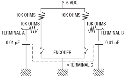
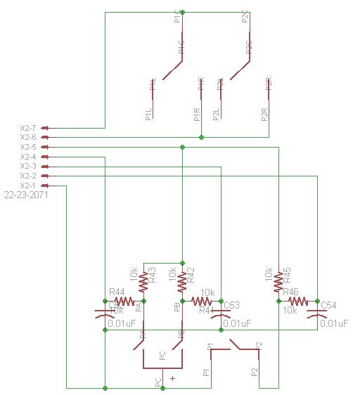
On left, the filter board schematic taken from the PEC11R encoder datasheet. On right, my version of the schematic drawn in Eagle.
Following routing, the filter board is complete.
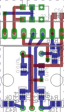
The board drawing
Now on to the case. Since it will be 3D printed there is a lot of leeway in the design. I used the 'web' feature to save plastic (and printing time) while retaining structural rigidity. The case consists of three parts: the LED holder, the battery+circuit holder, and the battery cover. There is a gap between the battery holder and LED holder, to allow air circulation through the heatsink (this is done more for style than actual heat transfer as the LED does not get that hot). The LED listed in the supplies already has a focusing lens and also a square aperture such that the output light pattern is a square shaped beam that expands at 10 degrees. To match this square aspect visually, the case also has a square cross section which is aligned with the LED beam. The rendering below shows the pertinent features.

CAD of the case that will be 3D printed. On left is the LED holder, which interlocks with the battery holder in the center, and on right is the snap-in battery cover.
After sending the filter board for manufacture and 3D printing the case components, all the parts are assembled. First the LED and heatsink are inserted into the LED holder. The web elements of the case hold the LED in place (they are drawn in CAD to exactly match the dimensions of the LED, which in practice results in a reasonably tight interference fit since the edges of 3D printed parts extend beyond their nominal dimensions).
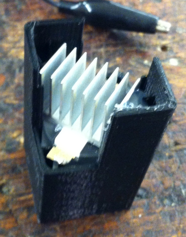
The LED is inserted into the LED holder (bottom end of LED is visible). Then the heatsink is placed on the LED's heat transfer pad.
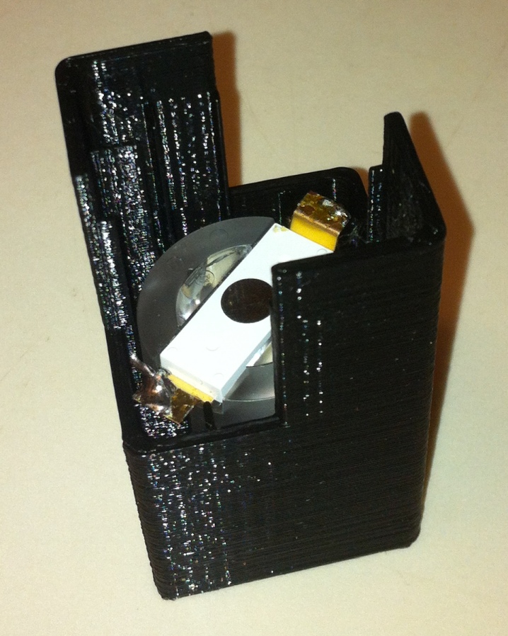
Next the electrical components are placed inside the case. The tricky part is getting the wires to the LED out from the bottom of the case, and also ensuring there are no shorts as all the components are in very close proximity. For this reason I put some tape on the outside of the 9V battery so it would not get scratched by exposed leads.
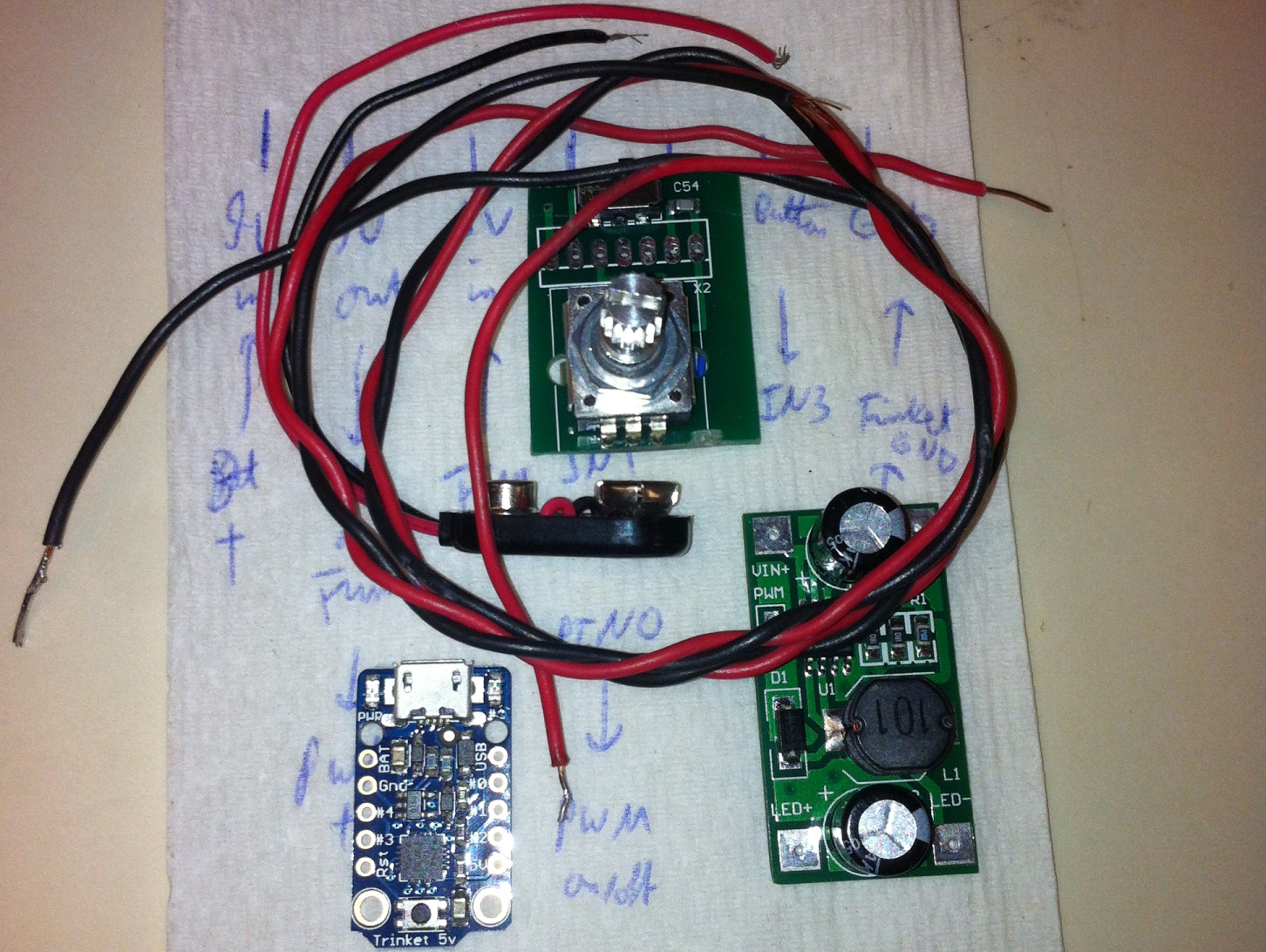
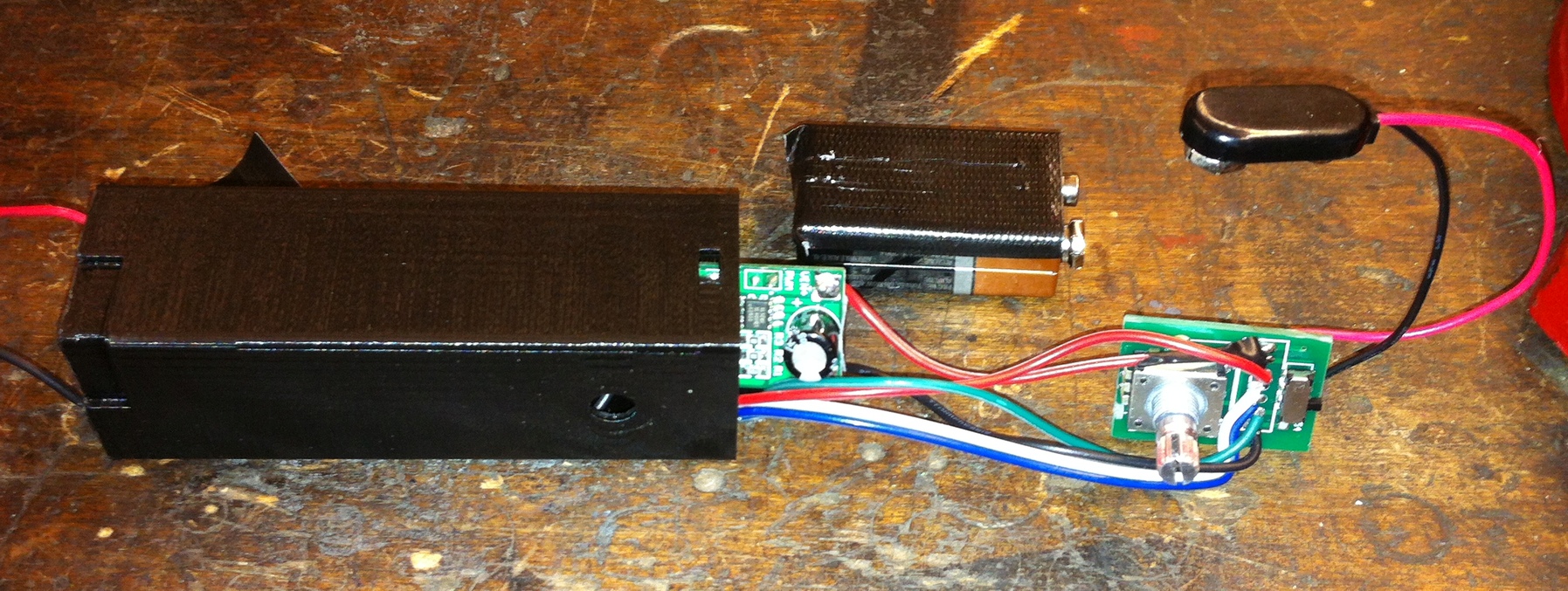
The circuitboards are obtained, then connected using wires soldered between the required pins, then everything is stuffed into the second part of the 3D printed case. The red and black wires extending out from the case will go to the LED.
Finally the battery cover is snapped in place, the LED power wires are soldered to the LED, and the two case halves are glued together. That wasn't as hard as I thought! This is my first time trying out a 3D printed case and I like it (though it takes a fair amount of time to do the CAD).
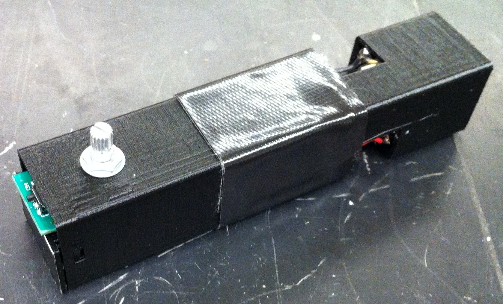
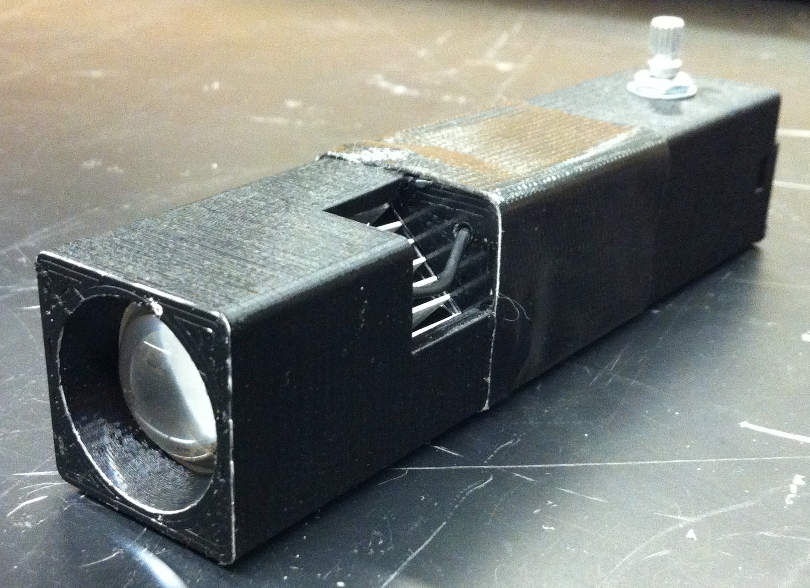
Back and Front views of the completed strobe light.
In this project the control knob should adjust either the duty cycle or the frequency (selected by quick push of the button), and also the controller should output the current frequency as a numeric Hz value (selected by long push of the button). First we need to handle the inputs from the encoder.
The encoder is useful as an adjustment knob with microcontrollers as it does not require an analog to digital converter (as opposed to a potentiometer). Thus the effective resolution of the encoder can be chosen in software based on the application requirements. In this case, the frequency resolution changes logarithmically so that it is always a fraction of the frequency (about 1/200). However the duty cycle resolution will be linear since the range is not as large.
As mentioned above, there are two pulse outputs from the encoder. Those are wired to the trinket pins 1 and 2. Writing the two encoder output digital values as (00) or (11) we track the pattern as the encoder is spun clockwise: (00)-(01)-(11)-(10)-(00)-... Now spinning it counterclockwise: (00)-(10)-(11)-(01)-(00)-... which is the reverse of the previous pattern. So by detecting which of the two patterns is seen by the microcontroller, we can tell whether the knob is being spun clockwise or counterclockwise. And with each change in the measured values, we know that the knob has been turned by one 'unit'. This section of the code converts the encoder pattern (00)-(01)-(11)-(10) into the incremental (00)-(01)-(10)-(11) which is the sequence 0-1-2-3 in binary.
if(digitalRead(1)){//convert to 0-3 index
  phase=0x03^digitalRead(2);
}else{
  phase=digitalRead(2);
}
From this point, the program checks whether the counter phase has incremented or decremented and acts accordingly. I use the variables TCCR1 GTCCR OCR1C OCR1B to set up the internal hardware timer to output a PWM signal. This is mostly to save the trouble of programming a dedicated counter - since the hardware timer is only 8-bit the resolution is actually quite low. Going over the variables one by one:
The limited resolution of the timer places some constraints - namely we need to take advantage of the time scaling in order to have both reasonable resolution and a wide frequency range. Because the timer prescaler can make the timer slower/faster by a factor of 2, we note that having OCR1C=255 at full speed is equivalent to having OCR1C=127 at half speed. To have the highest resolution, we want to keep OCR1C high (imagine the timer runs at 256Hz, then with OCR1C=254 or 255 we can select between 255 and 256Hz, or 1/255 relative resolution. Now with OCR1C=0 or 1 we can select between 1 and 2Hz, or only 1/2 relative resolution). Thus in the software, as OCR1C decreases below the value 127, the timer is sped up (with a limit of 500kHz, TCCR1=5) and OCR1C is set back to 255. All the adjustments are done on secondary variables so that the writing to the timer variables can occur in one step.
if(timerFreq>127){
  timerFreq--;
}else{
  if(timerScale>5){
    timerScale--;
    timerFreq=255;
  }
}
Similarly, when OCR1C is increased beyond 255, the timer is slowed down and OCR1C is set to 127. This provides a continuous logarithmic (base 2, ~1/200 relative resolution, about 13 knob turns total) scaling over a fairly wide frequency range of 1.9Hz to 1.9kHz. See this excel spreadsheet for the pertinent values.
Duty cycle is much easier to adjust - it simply needs to vary between 0 and OCR1C in a linear way. Since the above code modifies OCR1C and timer speed, the duty cycle adjustment keeps an internal float value from 0 to 1 that stores the desired duty cycle (corresponding to about 2 full knob turns), which is then multiplied by OCR1C and converted back to a byte value to store to OCR1B. Since float multiplication is an 'expensive' operation, this is only done whenever either the duty cycle or the frequency changes. A limit condition ensures that the duty cycle can reach exactly 1.0 or 0.0.
if(dutyCycle<1.0)
  dutyCycle+=0.005;
else
  dutyCycle=1.0;
Finally we need a way to figure out the strobe frequency in Hz and output that from the controller. We calculate the actual frequency by using the timer speed in Hz based on the prescale factor, and divide that by the timer frequency OCR1C.
We communicate the frequency to the use also through the LED, which the controller will flash in a certain pattern. The LED will flash corresponding to the digits of the frequency written in Hz, with a delay in between the digits. So for 23.5 Hz the flash pattern will be **-***-***** with each '*' representing a flash and each '-' representing a delay. It is difficult to represent zeros in this case, so a zero will be output as a short flash '^'. Then for 1024.0 Hz the pattern will be *-^-**-****-^. This conversion is straightforward but forms the longest section of the code.
The complete code is available here: Strobe_Code.ino. Note that the Trinket bootloader needs to be selected, such as detailed on AdaFruit.
It works well! The case is sturdy, the battery cover actually snaps in place, and the timer scaling works as expected (although there are some occasional flashes when the timer speed is changed since the timer is not reset properly - for instance it may run to 255 for one cycle whereas it is only supposed to run to 127 if upon changing timer speed the counter is already above 127). However the 256-bit timer resolution, even with the dynamic scaling, is still too low for demanding applications like synchronizing the strobe to a camera's shutter speed. Maybe in a future revision I will add a higher resolution counter since the microcontroller is certainly capable of that.

Taking a photo of the strobe light as it is moved across a surface reveals the individual flashes of the LED. The square shape of the LED beam is apparent.