Variable Duty Cycle LED Strobe Light
February 19, 2013
Idea
The idea for this project came as a natural continuation of the previous LED strobe light which used 24 LEDs and an associated circuit board with a 555 timer for the strobe effect. That project, while working, was quite bulky and fragile, and did not look well made. As I have found that form can very well be more important than function, I invested time into making an LED strobe light that would be rugged and sturdy for continuous use and would look good. Since I was redesigning the entire circuit, I decided to add in a neat feature to allow control of the strobe duty cycle as well as frequency, thus it would be possible to have very brief strobes that would make objects appear to move in discrete steps, but also possible to have longer strobes which are brighter and more easily visible. The result was well worth it, as it is cool to have a flashlight with not one but two control knobs along with the traditional on/off switch.
Supplies
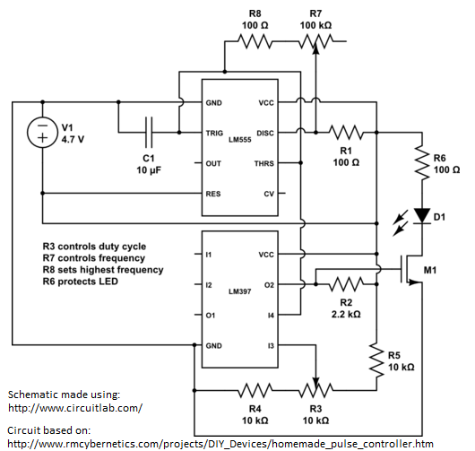
The circuit is essentially a variable frequency PWM controller, working at the low frequency range (about 1-60 Hz), and thus it is quite similar to the circuit designed by rmcybernetics with a few modifications in the capacitor and resistor values as well as the MOSFET used.
- LED Spotlight 3W/5W/more? This is the heart of the device as it contains the battery, high power LED, and most importantly the handle that can contain the control circuitry
- LM555 and LM397 chips along with a 16-pin DIP plastic connector for soldering
- Small circuit board, wires, resistors, 10uF capacitor
- 10kOhm linear and 100kOhm log variable resistors (potentiometers) (similar values will work also)
That essentially completes the project. The most difficult part is fitting the circuit in the limited space available inside the spotlight, and integrating it along with the other hardware already there (ie switch and battery charger).
Construction
First, the LED spotlight was taken apart. This was more difficult than expected due to multiple plastic pieces covering the screws keeping the assembly together, but after a bit of prying the spotlight could be split into two parts with the internal electronics easily accessible. The spotlight contained a 6V lead acid battery as the power source and had an LED assembly of an unidentified power (it had a sticker where a check mark could be placed by the power level of the LED, but there was no check mark there, probably means it is the lowest power) along with a board that contained circuitry to charge the battery from a power connector as well as a very rudimentary brightness control that would have to be replaced. In order to bypass the brightness control but still allow battery charging, I disconnected the LED and the on/off switch from the board but kept the battery and power connections. That way the built-in circuit board would be used for battery charging only, while my custom circuit would handle the LED.
Next it was time to put together the LED controller circuit. The MOSFET used in the circuit was chosen so that it would be able to handle the power requirements of the LED - the data sheet for the MOSFET claimed 30A of current which is more than enough, I only bought such a high current device because it was cheaper than a lower current model! The fact that transistor technology has advanced so much is quite amazing.
This circuit uses both an LM555 timer and an LM397 voltage comparator. You may notice that the output of the timer chip isn't used, this is because the comparator's output is driving the LED. Essentially, the 555 timer will charge and discharge the 10uF capacitor through the resistors, and each of those cycles counts as a 'flip' of the output voltage. The 100kOhm logarithmic variable resistor controls the strobe frequency and should be wired so that the faster rate of change occurs at the higher values of resistance, as with lower resistance values the charge/discharge frequency increases and finer control is necessary.
In order to allow a variable duty cycle, the voltage directly across the capacitor is taken and compared with a reference voltage in order to set the duty cycle. By adjusting the reference voltage up or down, it can be seen that the output of the comparator will remain positive for shorter or longer, respectively, while still turning on and off at the frequency of the 555 timer. If you picture the charge on the 10uF capacitor as approximately a triangle wave, ranging from a to b volts with the frequency determined primarily by the 100kOhm variable resistor, then the 397 comparator will output a positive signal 100% of the time if the reference voltage is lower than a, and will never output a positive signal if the reference voltage is higher than b. In-between the two voltages there is a continuous range of duty cycle values that can be set independent of the strobe frequency.
In summary, the 100kOhm variable resistor adjusts the frequency of the strobe pulses, while the 10kOhm variable resistor adjusts how long each pulse will last roughly as a percentage of the time until the next pulse. Thus the circuit provides a variable duty cycle as desired in the beginning.
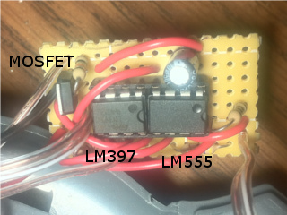 The completed PWM strobe circuit on a compact breadboard
I was happy with the size of the circuit as it took a measly 14x8 piece of circuit board, compared to the old 24-LED experiment that ungracefully expanded over an entire breadboard space. This small piece was made to fit inside the handle of the LED spotlight, which previously contained only air and empty space. Wires were added to it to connect to the variable resistors that would be accessible from the outside of the spotlight (in place of the old clunky brightness control buttons) as well as to the LED bulb itself that had a built in resistor so there was no worry about burning out the LED.
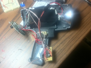 The strobe controller has been integrated with the spotlight circuit and is about to be sealed inside the frame of the spotlight
The circuit and associated components fit quite snug within the LED spotlight, and the light assembly was put back together. As expected and hoped, it turned out to be very sturdy and robust, and looked at least half-way professionally made. While knobs on the variable resistors would have been nice to complete the form aspect they are still usable without the knobs and structurally are not disadvantaged. This strobe light design is sure to last a long time, since the circuit internals are quite well protected inside the multiple layers of plastic that make up the spotlight (now strobelight).
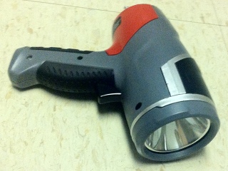
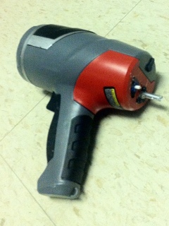 Two views of the completed strobe light project, front showing the high intensity LED along with the on/off trigger on the handle, and back showing the two potentiometer knobs used to control the strobe frequency and duty cycle
Results
The quality of the strobe itself is quite good, at the lowest duty cycle it is dim but once your eyes adjust to the decreased light output the strobe quality increases greatly as objects can be seen clearly (such as water droplets falling from a faucet). Increasing the duty cycle causes objects to appear more blurry as the LED stays on for longer and longer, until eventually at 100% duty cycle the strobe light becomes a regular LED light. Varying the resistance of the frequency potentiometer of course also has the desired effect, and it is fun to try tuning the strobe frequency so that moving objects appear still (such as a spinning fan).
Overall the project was a success and the strobe light now has a definitive solid package that will not easily fall apart like the previous taped-together designs. The circuit used is a lot smaller than before while actually having more features. I am sure the resistance and capacitance values could have been fine-tuned to get an actual 0-100% duty cycle (this design is maybe 5-95%) and a more desirable frequency range, but I cannot complain of the frequency and duty cycle range that this particular circuit has resulted in.
Ultimately, it is cool to have a flashlight with a 'strobe speed' knob but doubly cool to also have a 'duty cycle' knob. This is a very awesome strobe light indeed.