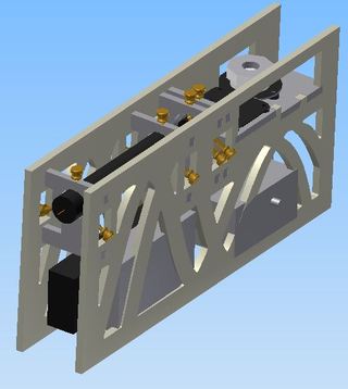
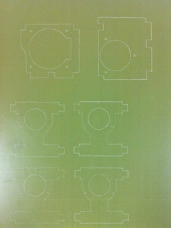
CAD model of the project.
Most of the supplies for this project were from scrap, in fact the only things I purchased were the plastic bolts and standoffs. The concept of this project is to make an easily adjustable stand for the main components of the laser oscilloscope system, which are: laser, focusing lens, collimating lens, and reflector. All of these components are attached to the rigid frame using a combination of 3-DOF axial bolt supports and 2-DOF compressed rubber spacer supports, so that they can be adjusted as necessary. The supports for the laser and focusing lens allow the adjustment of laser beam angle and laser beam translation, while the collimating lens and reflector allow for adjustment of angle and height with respect to the laser beam.
CAD model of the project.
The first part to fabricate was the circuit to drive the reflector motor. This project uses a brushless motor, because it can be controlled to run at a precise velocity based on the frequency of the applied voltage, unlike a brushed motor which, if unloaded, will generally not run reliably at an intermediate speed. In this case there is essentially no load on the motor, so a brushed motor would not be an appropriate choice. The controller used here is an open-loop variable frequency 3-phase output, with the frequency determined by a potentiometer input. The controller uses 3 flip-flops running from the same clock source (the speed of which is based on the resistance input), and the flip-flops are chained so that the input in one phase is the inverse of the output of the previous phase. This sets up a pattern like: 100 110 010 011 001 101, and looking closely it is evident that each of the phases is on for 3 of the 6 variations in the pattern, or 50%. This is a closer approximation to a sine wave than the simpler input-output chaining that would result in: 100 010 001, and thus will achieve smoother speed control. The circuit was tested on a prototype board, then drawn up in Eagle, then printed and etched on a one sided board.
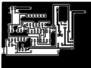
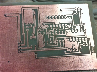
The circuit drawing from Eagle as printed on wax paper and transferred to the board, and then the board after etching and drilling holes.
Placing the components on the board ended up being a bit more messy than I expected, partially due to me being used to working with solder masks, and partially because there were ground connections that needed to be made on the bottom of the board (yes, that is by design, to avoid wires on the top of the board). In any case, the circuit worked as expected except for some bad joints on the timer chip, which cause response problems from time to time. Re-soldering should fix this but I would recommend not soldering the ICs directly because they are difficult to replace.
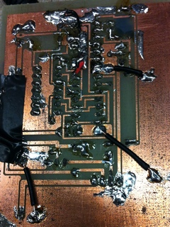
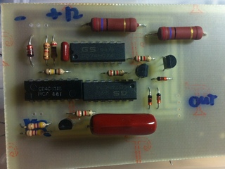
The back and front of the circuit board with all components placed.
The next challenge was the octagonal reflector. This seems like quite a useful piece as it sweeps out a 90-degree angle from an incoming laser beam, but I could not find anything relevant available for purchase. Reflectors used in laser printers are usually square and very thin, while this reflector needs to be thick to support the variation in beam angle due to the oscilloscope signal output. I cut this piece on the waterjet out of the same 3/8 in. Al stock used for the weapon for Candy, then went over all the external faces on the mill to ensure they were reasonably flat, then polished each side by hand (using a polisher though), starting from 240 grit wet sanding, then 480, 800, 1200, 2400 grit, and then 9um, 3um, and 1um diamond suspension to get the shiny mirror finish, which is still not as flat as a proper research grade mirror but good enough for the application. A major problem is the variation of angles between different flat faces, causing what is supposed to be one line to appear as a multitude of lines. This is still an issue here, because strangely the polisher provides no means of holding the sample at a particular angle. The deviation was observed to only be slight, and when a waveform is displayed it will likely not matter.
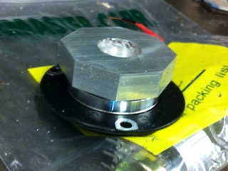
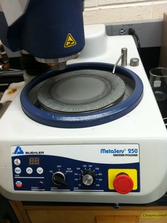
The octagonal reflector after milling, and the polisher used to get a mirror finish on the external faces.
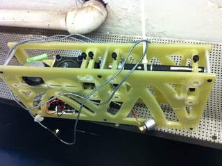
Following this, the actual supporting structure was to be cut out. I found a large sheet of some material that was unwanted, and seemed to be perfect for this project. As it seemed to be easy to cut, I printed out to-scale drawings of the components to be cut out, taped the drawings to the sheet, and traced out the lines with a knife. I was hoping to use a dremel with a carbide cutter to cut along the traced lines, but as soon as I started there was significant resistance. The material would not bulge unless significant force was applied, and within a few minutes smoke started to come up from the cut area - the carbide cutter was dull! I guess in all my luck I picked out a fiberglass composite, thinking it would make for an easy-to-machine project material.
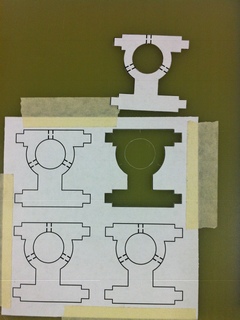
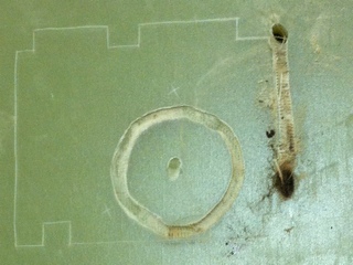
Part outlines were traced with a knife, leaving a nice clear outline on the material. Trying to cut it with carbide caused a fiery mess!
I had to end up cutting the material on the waterjet, where it still managed to slow down the project by swelling near the cut edges where pressurized water may have entered between layers of fiberglass and epoxy. The swelling required using a dremel to sand down all fit edges so that they would have the intended dimensions.
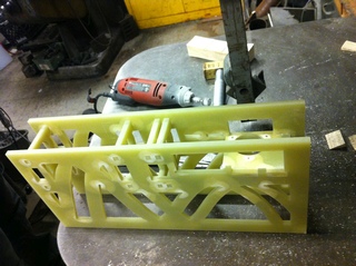
After lots of sanding, all parts fit together.
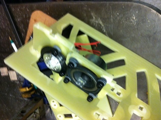
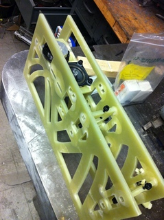
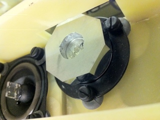
The speaker and reflector are added to the assembly.
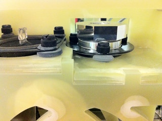
A closer view of the focusing lens and scanning octagonal mirror.
After the main parts were set up, the amplifier was connected to the speaker and the motor controller was connected to the scanning mirror motor. With the electronics in place, the two lenses and reflector were aligned so that the laser beam would be appropriately focused and incident in the middle of the scanning mirror when the speaker was not moving (this enables the maximum angular range to be reflected by the scanning mirror). All optical parts mounted to the fiberglass assembly are adjusted by plastic thumb screws, and the speaker and reflector have rubber spacers to allow adjustment with a vibration-free fit. The flexibility afforded by this design made optical alignment fairly straightforward.
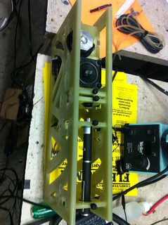
The laser is placed in the aligned assembly and the construction is complete.
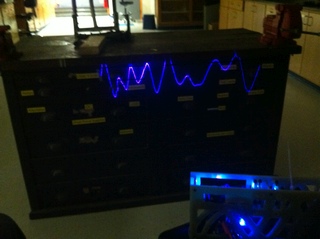
Time for some testing! It was quite successful, as expected from the earlier tabletop trials, and the assembly was solid and portable enough to carry around and still maintain the optical alignment. A video can be seen for the sort of results obtainable (song Introspection by mind.in.a.box). The response is largely to low frequencies, but it is still satisfying to watch! Note that the camera used was quite sensitive and a lot of the light-blue haze around the laser beam is not visible to the eye, so the trace appears much cleaner in reality than on the computer screen (the haze is caused by imperfections in the reflector surface finish, there was some trouble polishing with the 1um pads that caused a few scratches to appear). The scan direction is right to left, because the hard drive motor was observed to work better that way. The trace is a representation of the actual motion a speaker takes when playing music, which makes it much less abstract than watching a computer visualization (this also shows that sine waves and such have an importance in sound!).
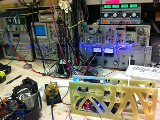
Testing the laser oscilloscope reproducibility in two different labs.
The following is a qualitatively measured relative frequency response. In the table, a larger response means that at the same peak to peak voltage sine wave input to the oscilloscope the laser's oscillations for that frequency appear to be larger than for other frequencies (which is a distortion of the true signal). It is clearly far from uniform, so this arrangement is not the best choice for very fast or precise tracing.
Relative Qualitative Frequency Response of Laser Oscilloscope

Frequency	Response
10 Hz		0
20 Hz		1
50 Hz		3
100 Hz		5
100 Hz		5
200 Hz		6
300 Hz		4
400 Hz		3
800 Hz		1
1000 Hz		0.5
2000 Hz		0
The video of the frequency response test can be seen here; it shows the oscilloscope reacting to an audio file that has a constant amplitude waveform with linearly increasing frequency of 0 to 628 Hz over 50 seconds.