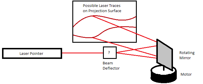
The problem of making a laser oscilloscope is illustrated.
The concept of a laser oscilloscope arose from the need for a good music visualization system. Various media players have a 'scope' visualization, but the digital processing required for that places it a bit further away from the original music than would be satisfactory. If a laser beam could be made to deflect due the motions that a speaker makes while playing the music, a laser-based oscilloscope using any wall or object as its projection surface, will provide a more authentic visualization. The original idea was to enable a 360-degree laser trace so as to cover all walls of a room, but due to the sound frequencies involved this is not practical without sound processing.
The original idea for this concept occured four years ago, at which time I did not appreciate the precision required for a high quality image. The various difficulties involved caused this project to be put off for a few years, with the LED music visualizer project serving as a substitute.
It is important to be aware of the design challenges in this project. There is a certain precision required for keeping a laser beam tightly collimated (collimated means the laser 'dot' size does not change even if it is pointed at a far away object, unlike a flashlight or lamp which are uncollimated. Passing a laser beam through a lens can make it uncollimated and act like a flashlight of a very specific color.). The first implementation involved a mirror mounted on a speaker so as to pivot about a certain angle as the speaker moves up and down. This change in angle of the mirror deflects the laser beam, and a second rotating mirror traces the signal over the projection surface at a certain speed. (In other words, the first mirror controls the Y-axis location of the laser beam and the second mirror controls the X-axis location).
The problem of making a laser oscilloscope is illustrated.
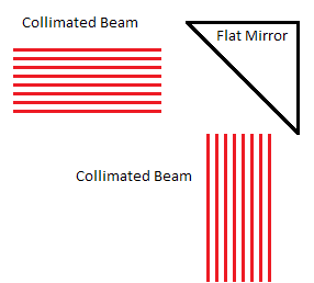
Optics basics: a collimated beam is reflected well by a flat mirror and poorly by a curved/unpolished surface.
While the concept worked, the variation in angle due to the mirror on the speaker was quite limited and thus waveform traces were difficult to see. The rotating mirror proved to be a challenge as well, on multiple accounts. First, finding a mirror of a proper size and attaching it to a rotating platform was difficult. After some experiments with small glass mirrors, I purchased a roll of reflective plastic sheet, which allowed me to control the reflector shape but introduced significant bends which caused the laser beam to spread to a blurry area rather than a concise dot. This blurring combined with the small visualization amplitude resulted in waveforms that were barely visible and had poor optical quality. Second, the orientation of the mirror was difficult to set up correctly. If the mirror surfaces are not strictly parallel to the axis of rotation, there will be a different Y-axis 'zero point' for each mirror surface, so multiple traces will appear at different heights. This causes the trace to look rather inelegant, especially when showing a no-signal input and multiple lines appear. Third, the proper rotation speed is difficult to achieve. Most commonplace DC motors are either ungeared and are too fast, or geared and are too slow, for the proper frequency trace. If the motor is too fast, a single wave may be stretched out over multiple walls and be impossible to observe - the result will look simply like a straight line moving up and down. If the speed is too slow, the individual waves will blend together and the result will look like a blurry trace (this is typically also too slow for persistence of vision to create the illusion of a trace line, so only a part of the projected area will be used at any time).
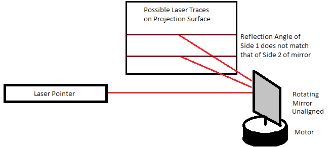
The problem of rotating mirror misalignment (causing a split in trace lines) is illustrated.

The properties of various rotating mirror types are shown (2-sided, 4-sided, 8-sided mirrors).
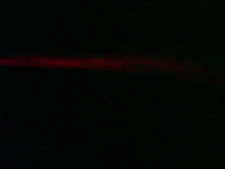
What happens when the rotating mirror is too slow (left) and too fast (right).
The problem associated with the rotating mirror could be solved with proper component selection and alignment. However the problem of deflecting the beam along with the speaker motion proved to be a challenge. If a regular mirror is attached, it must have a pivot about which to change angle. Simple experiment may show that moving the mirror up and down will not deflect the laser to any appreciable extent, regardless of the mirror angle (since the angle of laser reflection is based only on mirror angle, not its location). However any assembly using readily available parts to create a pivot on the outside of the speaker and a moving frame attached to the diaphragm will be heavy and have high inertia, thus being unable to trace higher frequencies and unfavorably affecting speaker (and trace) performance even at lower frequencies. Furthermore having a large mirror assembly on top of a speaker is rather shaky and inelegant unless custom components are made for the task. My first attempt used household items and was an eyesore, with outgoing laser beam quality to match since the parts had to be loose mechanically in order to faithfully follow the movements of the speaker surface.
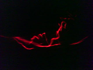
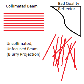
A physical manifestation of a poor quality reflector (left) and poor beam collimation (right).
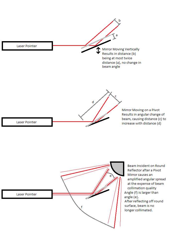
Consistent deflection of a laser beam is difficult to achieve. The first option of a moving mirror has little effect. A pivot mirror works but is not elegant. A curved reflector causes the beam to lose collimation.
One possibility for producing a visible beam deflection is to amplify the original deflection from some regular reflector, such as a mirror moving up and down (not on a pivot). This could be done by shining the laser onto a reflecting rod, which causes the reflection angle to change as a function of incident angle thus amplifying the deflection. The problem with this approach is that the collimated beam becomes an unfocused beam as a result, and to maintain beam quality the rod's surface should be as flat as possible thus reducing the amplification effect.
Another possibility occurred to me a few months ago, involving the use of curved reflectors. The concept is similar to the reflecting rod above, but the laser beam would be incident on the inside of the rod surface rather than the outside. The defocusing of the beam due to the curved reflector can in this case be minimized by using a second curved reflector. The beam would hit one reflector (ideally a parabolic mirror, realistically a circular approximation) and be brought to focus on one spot after which it would spread again. Then it would be incident on the other parabolic mirror (that is moved up and down) which would ideally re-collimate it for no deflection or almost re-collimate it for a vertical deflection of the mirror. With this setup, the collimation of the beam is nearly maintained throughout the deflection range, and an amplification of angular deflection is realized.
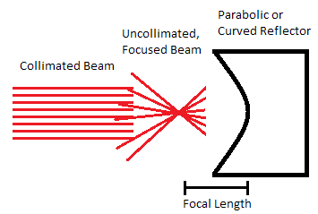
A curved reflector focuses the collimated beam, or collimates a focused beam if used in reverse.
The difficulty with the curved reflector setup is that such curved reflectors are not readily available. After attempting to machine some using a mill, rotary polishing tool, and aluminum blocks, I have found that making an optical-quality finish that would be good enough for the laser is difficult to do without specialized tools. Even though the polished mirror surface looked good to the eye, the nature of the setup requires a tightly focused beam to interact with a very small spot on the reflector, and with the laser beam all tiny imperfections of the reflector are revealed. While theoretically a workable concept, this approach cannot be done with everyday materials. Another difficulty is the weight of the curved reflector, most likely a solid metal block, which will again negatively impact speaker performance.
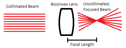
A convex lens focuses the collimated beam, or collimates a focused beam if used in reverse.
The final breakthrough in this project was due to a mathematical crossover from curved reflectors to convex lenses. Physically, a convex lens acts like a parabolic reflector, bringing the beam to a focus at some focal length outside the lens, except it does not reflect the beam in the process. A second convex lens can be used to re-collimate the beam. If this second convex lens is made to move up and down vertically, the curvature of the lens surface will provide the required angular amplification while the lens itself will serve to almost collimate the laser beam (beam quality getting slightly worse as the deflection increases). What makes this arrangement attractive is the relative ease of obtaining small convex lenses, and the ease of attaching one to a speaker diaphragm (along with its light weight if a small plastic one is used).
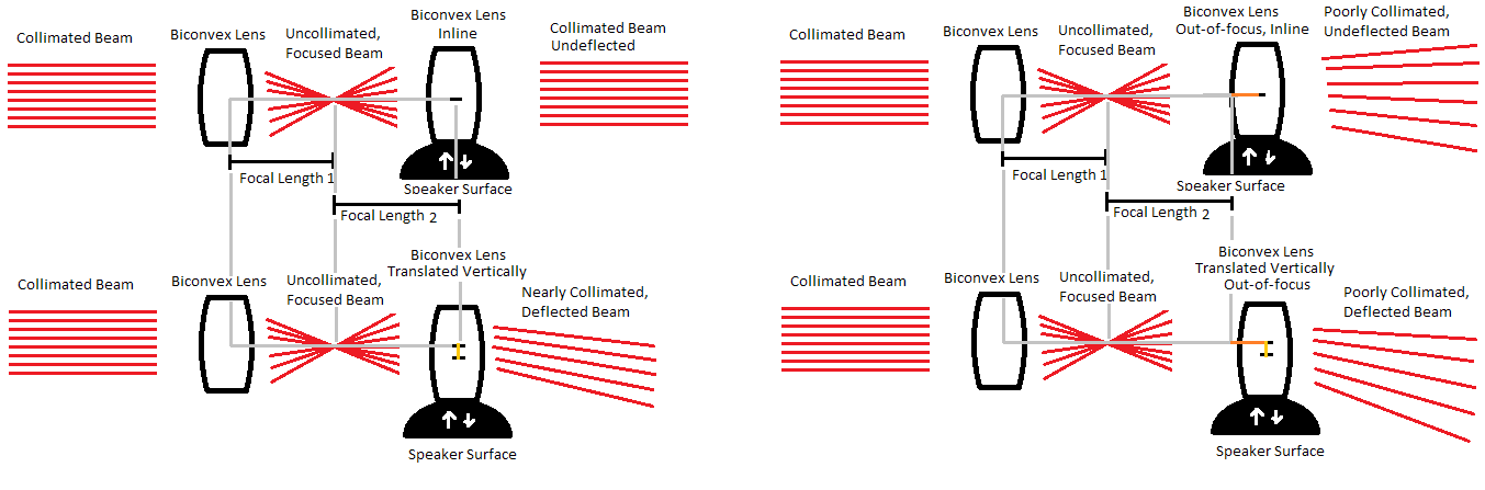
An overview of the final project concept. Two convex lenses that are aligned properly will cause a collimated beam to maintain collimation. If one of the lenses is moved vertically, the beam is deflected and slightly uncollimated. If one of the lenses is moved horizontally, the beam becomes unacceptably uncollimated but may still be deflected.
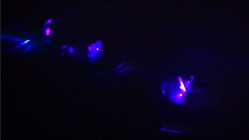
The prototype project is shown, from left to right: stationary convex lens, moving convex lens on top of a speaker, and rotating mirror assembly.
The prototype project works successfully! See attached video of prototype (music: Tel Aviv by Apparat) and final project.
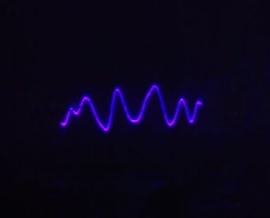
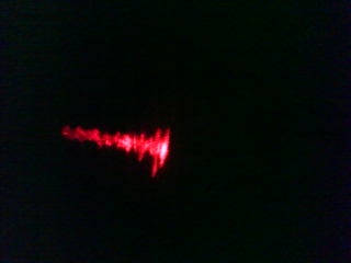
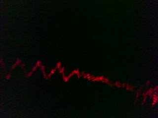
A sample trace of the oscilloscope, showing the high optical quality attained.
With these optics, it was possible to get very high beam quality, making this laser oscilloscope comparable in visual quality to digital visualizations. Its response is of course instant and always synchronized with the sound on the speaker. As can be seen in the video, it is not responsive to high frequencies, but quite responsive to bass and somewhat responsive to mid-level frequencies. This is caused by the ear's sensitivity and soundwave energy content, which requires the physical speaker movement amplitude to decrease as higher frequencies are attained for the sound to be heard at an equivalent loudness. In other words, if a high frequency note were played with the same amount of speaker deflection as a bass note, it would be painful to the ear but then visible on this oscilloscope. This additionally explains why finer details can be seen with the oscilloscope as the sound level output to the speaker is increased.