This guide is intended to provide the reader with a mental approach to questions in optics that will result in a physically accurate interpretation of the situation of interest. Such questions may be: how does the eye form an image, what is the difference between a magnifying glass and a microscope, how does a film projector work? For understanding these situations, an essential view asserts itself: that optics must be seen as field phenomena - propagation of 3D wavefronts in a spatial volume - so in the physical descriptions below I will never use the word "photon". I think the present trend of flippantly calling anything involving light as "photons" is a major blunder in the educational and scientific materials, because a meaningful mental construct that corresponds with all experimental results can only be achieved by treating light as 3-dimensional field oscillations. (Then, I might add, one questions whether "photons" are physically real or an artifact of human cognitive biases when interpreting results - I believe the latter. The photoelectric effect, for instance, only demonstrates that something in the experiment is discrete, not at all that "photons" are discrete.) With that in mind, I would invite the reader to imagine a filled 3D volume, such as the inside of a cube, and visualize waves propagating as expanding spherical shells inside this volume - for example pressure waves in water during an ultrasound scan. These waves can reflect off the boundaries and walls in this volume, in which case the spherical shells still expand in radius but change their direction of expansion. Or the waves can be absorbed by the boundaries and walls. While the wave patterns can be complicated, their behavior within the free space volume will be identical - expansion along their existing wavefronts; as far as light is concerned, propagation in any volume of empty space will be the same as in any other. It is a matter of separation and relative locations of the walls and boundaries that defines how solid objects in the volume interact with the wavefronts - such as when we use a camera to photograph a landscape. Really, what we are capturing in the photograph is not the landscape, but the volumetric field configuration in a very thin volume immediately in front of the camera's digital pixelated sensor or its light-reactive chemical film. The lens of the camera, and just as importantly the solid opaque structure that holds the lens in place and blocks out any incoming light except that passing through the lens, serve as a means to link the tiny volume of field at sensor surface to the wave emitter relative positions in field far away from the camera. The "far away" aspect indeed relates to far-field propagation, and is why optical instruments cannot exceed the diffraction limit, which relates to the wavelength of field waves (imaging in excess of this limit, "super-resolution" microscopy, is possible when placing a lens element below a wavelength in size next to the sample, thus using near-field information). With this mental construct, we can verify and extend our intuition of the field by considering some practical examples.
Probably the simplest way to make an image is by using a hole (and, as well, the opaque solid enclosure which defines the hole by blocking free space field propagation around it). What is interesting in this situation is that an optimum hole diameter exists, as we will calculate below. For now we will define an image as a 2D projection of the 3D locations of wave sources. Wave sources, in turn, represent an energy input into the field (the waves in the field have an inherent directionality of energy transfer - an incoming wavefront is distinct from an outgoing wavefront, even in an overlapping volume). Looking at a photograph, or a computer monitor, the eyeballs achieve a mapping from the 2D surface outside the body to the 2D surface of the retina, which is then processed by the brain: in a way, an image of "an image" (the former in the optical sense of field energy concentrated along a planar slice, the latter as referring to a flat source array such as a photograph). If a piece of paper is placed behind an aperture (a hole in a large opaque sheet), at some distance an image of the scene on the other side of the aperture will be formed - looking at the paper you will see a "clear" scene projected at some optimal distance and an increasingly "blurry" scene at other distances, although "clear" here is a relative term. This can be done using a wall in a room as the projected surface, making a "camera obscura", which is a fun experiment to try at home or to see in some existing public installations (although these mostly use lenses rather than holes). Note that to do this at home, a hole diameter of about 2 mm can be expected for optimum resolution (calculations below), and the experiment should be done on a very sunny day because the light coming through such a small aperture will look very dim inside the camera room. Also, because the "desired" light will be so dim, it is essential to completely block out all other potential openings for light to enter the camera, which may prove to be a challenge for large rooms (I would recommend using aluminum foil, and starting in a room that has few windows / doors).
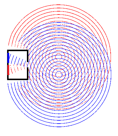
A schematic illustration of the pinhole camera principle. Two sources (red and blue) generate outgoing spherical waves which overlap in the surrounding space. After passing the aperture of the camera, the oscillations that make it through, continue propagation along the radial direction, resulting in two distinct areas illuminated on the back surface of the camera, corresponding to the red and blue sources.
Two parameters, the hole diameter and the distance from hole to observing plane, can be varied experimentally to test their impact on image clarity. Since the field is scale-invariant, we can expect that the ratio of diameter to distance is of interest: for a large distance, such as an entire room, a large hole can be used, which makes the experiment easily accessible without requiring precision machining - the hole can simply be cut out with scissors and progressively increased in diameter. For a smaller distance, such as a hand-carryable box, the hole should be correspondingly smaller and made with a pin or a needle, but then quantitatively changing the hole diameter is a bit more difficult with basic tools. In any case, for a large room we will need a large hole - which directly proves the field nature of light. If light were not a field, then making the hole smaller would always be preferred, yet it is experimentally observed that making the hole too small actually makes the image more blurry. Here we reach a diffraction limit, even though for a large camera obscura the optimal hole diameter may be over 1000x the wavelength of light, because the distance to the observing plane is in turn much bigger than the hole diameter. There is an optimal ratio of hole diameter to image distance for highest resolution, and if one understands why this is true, the accurate interpretation of other optical phenomena will come easily.
This situation can be analyzed mathematically by describing the wavefront measured at a particular point with two parameters: phase and amplitude (with known wavelength and unidirectional energy flow). Then, the image formed on the back of the camera is completely defined by an array of phase and amplitude values defined on points filling the 2D circle inside the hole. Note that this means the information limit on the image is set by the hole diameter, not by the size of the back surface. This is why the limiting aperture of any optical system is an important parameter to define: this aperture represents the largest unique field size and therefore real information capacity of the system, showing itself as a resolution or angular limit. With the pinhole camera there is only one aperture, that of the hole, and this is what sets the resolution limit (this limit is not actually reached, because no lenses are used to improve wavefront separation - but in exchange there is no focal plane so both nearby and distant objects are "in focus"). By this logic alone, a large sheet of paper will be a much higher resolution "camera" than a cardboard box with a hole, because the sheet has a larger area and therefore captures more field information, and this is true. The reason we make the box with a hole is because our sensing mechanisms are not sophisticated enough to capture phase and amplitude along a surface (this is, however, done in holography - and there, one may note, no lenses or apertures are placed in front of the light sensitive element). Amplitude by itself is much easier to record. What the box achieves is a conversion of phase information to 2D location, so the image has an appearance of all amplitudes of a particular phase relation in a specific area of the sensitive element. By carrying out this conversion, a specific perspective is imposed (unlike in a hologram, where the observer may see multiple perspectives). In a way, the pixels illuminated inside this camera are images of the hole modulated by the source, as much as they are images of the source modulated by the hole.
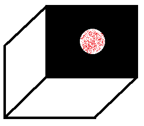
The red points, here schematically drawn inside the aperture of the camera, represent point measurements of the field wavefront at that surface. If these phases and amplitudes are known, the image on the back surface of the camera can be calculated by summation.
To calculate the appearance of the image on the back wall of the pinhole camera, we can consider for each point on the wall the field energy incident at that point from the field defined inside the plane of the aperture. That is, at a given detector point, we integrate over the aperture area adding up the phases and amplitudes (at constant frequency) inside the aperture and their contributions by distance to the detector point. Distance changes amplitude by r-2, and phase by r*(2*π/λ). Let's assume that all field points inside the aperture are at a constant phase and amplitude, which is representative of a very distant object or a laser beam normally incident on the aperture. Shifts in phase can then be superimposed on the input and output fields, resulting in an angular shift of the resulting image. Further, assume that the image plane is far enough back from the aperture that the change in angle from one edge of the aperture to the other is small. Specifically, the change in path length is dominated by the perpendicular component, and this change is a small fraction of the total path length. This means that the amplitude shift r-2 is approximately identical for all points in the aperture, and the phase shift r*(2*π/λ) is taken to be linear with distance across the aperture rather than quadratic.
At a point directly behind the aperture and on the same axis, the amplitude is expected to be maximal as the phase shift will be uniform across the aperture. Now if we move to angle θ from this axis, the phase shift will no longer be uniform, as some points inside the aperture will be further away from the detector than others. The phase shift can be linearized as dp=x*sin(θ), where x is the distance away from the central axis in the plane of θ. Further, the positive angular component of phase is given by cos(p) (using the positive component, we only need to integrate over half the aperture). Then, with aperture diameter d, at the first zero of the integral we have ∫0d/2A*cos(x*sin(θ)*2*π/λ) dx = 0. At this value of θ, there will be complete destructive interference of the phases in the aperture, and thus a dark ring will be seen. This is, in a rough sense, the diffraction limited "pixel size" or resolution of the pinhole camera. Ideally, for the uniform wavefront at the aperture, θ would be zero, but due to the finite camera size, θ is not zero, meaning small features become indistinguishable in the image due to diffraction. For a circular aperture, the amplitude A is proportional to the linear slice through the circle, particularly for the above integral, A∝√[(d/2)2-x2]. (For a square aperture, A is constant when θ is in the plane parallel to the square sides.) We can substitute B=sin(θ)*2*π/λ, then for the circular aperture ∫0d/2√[(d/2)2-x2]*cos(B*x) dx = 0. This gives a Bessel function, π*d/2*J1(d/2*B)/(2*B) = 0, or J1(d/2*B) = 0, or d/2*B = 3.8317. Substituting back for B, this gives sin(θ) = 1.22*λ/d, and for small θ, θ≈1.22*λ/d. (For a square aperture, θ≈λ/d, along the square sides.) Two different Scilab codes that demonstrate this integral numerically are presented: laser.sce aperture.sce.
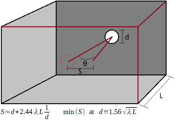
A diagram showing the variables used in the calculation.
The diffraction analysis above thus suggests that a larger aperture size d will always lead to a smaller θ and thus higher resolution. The principle is correct - it is why telescopes have such huge mirrors - but it has limited applicability here because in doing the calculation we have assumed θ is small. Therefore to find the optimal pinhole size we have to include a non-zero θ back in the optimization. Roughly, we can estimate that a pixel size in the pinhole camera is the aperture diameter plus the angular expansion over θ due to diffraction. Then, S=d+2*tan(θ)*L, or for small θ, S≈d+2*θ*L. From the above first-interference calculation, θ≅1.22*λ/d, thus S≅d+2.44*λ*L/d. As this is the sum of (d) and (1/d) terms, there is a minimum value of S when these are equal: d=2.44*λ*L/d, or d2=2.44*λ*L, or d=1.56*√[λ*L]. This is the formula for an estimated optimal pinhole camera aperture diameter d for a given back plane distance L and light wavelength λ. For L=3 m, λ=500 nm, we find d=1.9 mm. As claimed above, this diameter is thousands of times bigger than the wavelength, and it could be bigger yet if L is increased.
Next we will study the eyeball, because when we use optical instruments such as binoculars, magnifying glass, telescope, or microscope, the eye itself contributes to the optical pathway, and without an understanding of how an image is formed by the eye, the action of the instruments will not be clear either. The eye has an aperture, but also a lens to improve the focusing ability of the incoming field oscillations. The action is a mapping of spatial phase information (wavefront direction) at the pupil to particular angular locations on the retina, where an optical image is formed and light-sensitive cells process this image eventually resulting in conscious perception. So, let us begin with a general overview of lenses.
A lens is a refractive element, that is one in which the speed of wavefront propagation is different from the surroundings. For all glass optics in air, this speed will be slower inside the lens than outside. A wavefront incident on a region of slower propagation will change its curvature, because its wavelength will be shortened (as frequency remains constant). However upon returning to a region of faster propagation, the curvature will change back to its original form. Thus a flat pane of glass, as in a window, does not change the focal characteristics of what is seen through the window. A lasting change in the wavefront can be achieved by curving the surfaces of the optical element. This introduces a nonuniform spatial phase shift into the wavefront as seen in free space following the optic. Above, with the pinhole camera, we integrated the phase and amplitude over the aperture, with a possible linear phase shift applied as a function of θ. Using a lens, there is an additional phase shift introduced as a function of |x|, or the radius from the aperture center, which allows us to remove the d term from our definition of S by curving the wavefront inwards. Hence the optimization for S∝(1/d) now favors large d, and we can use large lenses to improve image resolution beyond the pinhole limit. With axial symmetry, there are two changes to curvature that can be made: increase and decrease. An increased curvature, from the point of view of the detector, means that the central part of an incoming wavefront is delayed relative to the edges, and hence a converging lens is thicker in the middle and thinner at the edges. A decreased curvature is the opposite, with the central part of an incoming wavefront sped up relative to the edges, so a diverging lens is thinner in the middle and thicker at the edges. But, if we increase or decrease the curvature with lenses, we limit the system to a particular range of curvatures, and therefore impose a focal length on the system: in a camera with a lens, there is a choice to focus on near or far objects but not both, and the larger the lens, the more prominent the distinction.
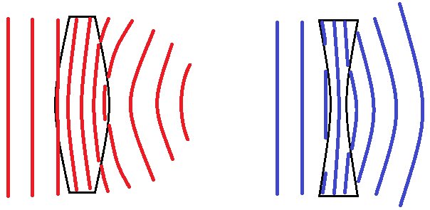
A highly exaggerated illustration of the action of a converging (left) and diverging (right) lens on a wavefront. This should be visualized in 3D for a complete picture. Where the field lines disappear, phase cancellation has occurred, though of course in real settings the cancellation is not complete so an Airy disc is formed.
From Snell's Law, we have n1*sin(θ1) = n2*sin(θ2). Because it is sin(θ) rather than just θ, at larger values of θ there is a shift from linearity. We can reason, then, that a more uniform performance will be achieved by minimizing the angle of wavefront incidence θ. Because of this, an asymmetric lens can have better or worse performance when oriented in a particular direction, which we will demonstrate below. However, to apply Snell's Law, we tacitly introduced the notion of a ray, for which the θ is defined. This needs to be examined closely, because it is easy to draw nonphysical conclusions from rays. Rays must be understood as useful approximations describing a very small (locally flat) cross-sectional area of a traveling wavefront in the field. To use the field in calculations, we require the field to be defined at sub-wavelength scale volumetric resolution, which becomes infeasible for practical optics. Thus we simplify the calculations by using rays, which are drawn along the normal directions of a particular small section of the expanding wavefront. What constitutes "small" depends on the context, which makes rays useful: each one represent the smallest useful (to the designer) unit of curvature, since each one defines the normal vector of a locally flat zone. For a large telescope the same rays can be bunched together over millimeters at the detector and spread out over many meters at the primary mirror, matching the high wavefront curvature at the detector and the low wavefront curvature at the primary mirror. In this manner, the large wavefront area at the primary mirror is handled mathematically without having to define it at the nanometer scale (though it should be appreciated that physically we do not have this shortcut - the real mirror must be shaped to nanometer precision over its entire area - which is why large telescopes are expensive instruments). Since the wavefront expands spherically in a uniform medium (in terms of the speed of light), the rays in free space and inside solid lenses are straight lines. (In optical elements with a spatial gradient of refractive index, GRIN lenses, the rays are curved. On cosmic scales, gravitational lensing curves rays in a similar manner. A big coincidence, perhaps, or a suggestion that the speed of light in space is not as uniform as we think.)
What is lost with the use of rays is diffraction effects and energy concentration. The pinhole camera analysis above is an illustration of diffraction effects, which show that we cannot make the aperture arbitrarily small - this could not have been proven with rays. Another example is of a lens concentrating light to a point: rays suggest that there is a single point that is formed, while according to wavefront interactions the point can be no smaller than a wavelength, and there will always be fringes around the main point (which appear as the Airy disc). This brings us to the energy concentration issue: rays are very easy to draw as emanating from or ending at a single point, but this has minimal physical usefulness. Amplitude in free space propagation falls as r-2, which may actually be a reason for pause. If I stand by a streetlight 1 meter away, and look at a streetlight 100 meters away, the energy reaching me from the latter is then expected to be 10000 times lower than that from the former, and yet to me both look equally bright. This is because brightness is not based on just energy, but on energy concentration; the light from the nearby emitter does carry 10000 times more energy, but this is spread out over a 10000 times larger area, and therefore its brightness appears the same. This is also referred to as "etendue", and implies that lenses cannot be used to enhance night vision, that is, to see objects that would otherwise be too dim. To put it another way, as long as the pupil of the eye sets the overall aperture of the optical path, it is not possible to "force" any more light to enter through this aperture than otherwise would, so objects do not appear brighter but may appear bigger. (It is possible to see more stars through binoculars than with the naked eye, but that is because their focal spot and incident energy are normally too small to activate a light-sensitive cell - not because they are "dim", since starlight comes from bright plasma - brightness is a function of temperature for a blackbody emitter and stars are hot. More discussion of this is under Stars in Daylight.) If we carry through the calculations of wavefront propagation in the field, all these energy flows will be accurately represented and thermodynamic laws will be satisfied. However if we forget that rays are representations of wavefronts, we may fantasize devices that violate thermodynamic laws and concentrate energy beyond the level of the emitter, which makes the image brighter than the source (physically impossible without amplification). This is because a point is an infinitely concentrated source, which can be mapped to any other concentration up to infinity. Similarly, we may draw ray traces through instruments that suggest resolution beyond the diffraction limit is possible (since a point defines an infinitely precise spatial location), but this would be another misapplication of rays, which by their nature ignore diffraction (the field diffracts whether we like it or not, enforcing a minimum spot size that we observe experimentally). Hence we should proceed cautiously to drawing ray diagrams in geometric optics.
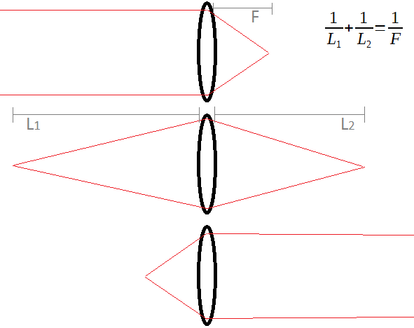
This image shows three possibilities of how the same converging lens affects an incoming wavefront, with the help of rays. A converging lens has a focal length F which is the distance at which a flat incoming wavefront is brought to a focus (point of highest spatial concentration of field energy). Objects that are very far away will be in focus when a detector is placed at the focal length. Objects that are nearer to the lens (like L1) can also be brought into focus, but then the detector needs to be moved further back from the lens (to L2).
Lenses are commonly categorized by their focal length, but I think a more physical approach is to categorize them by their wavefront curvature. To first order, we can assume the curvature is uniform, and for a spherical wavefront coming from a distance L, the curvature will be 1/L. Hence a lens can be designed to shift the curvature by -1/F, where F is called the focal length. A flat pane of glass has a curvature shift of zero, and making this pane slightly concave or convex will result in an increase or decrease of the curvature shift from zero. A zero curvature is more logical than the ±∞ focal length for the pane of glass. Furthermore, the curvature approach makes it easy to understand the thin lens equation: despite the limiting connotation of "focal length", a lens can image focused objects at any distance from the lens, though it is typically designed to achieve the highest resolution within a particular range. The lens will superimpose its constant curvature shift -1/F to all the wavefronts that pass through it. An object located at distance L1 from the lens will have an incoming curvature of 1/L1, and an outgoing curvature of 1/L1-1/F. This will make the outgoing wavefront appear as if it came from a distance L2, where 1/L2=1/L1-1/F. If we change the direction in which L2 is defined so it is on the other side of a converging lens, and then re-arrange the terms, we get 1/L1+1/L2=1/F, which is the thin lens equation. The "thin" in the name comes from an assumption we implicitly used that the curvature shift is small (F is much larger than the lens diameter).
The eyeball does not change in size (unlike a zoom lens on a camera), so the distance L2 between the lens and the retina is fixed. There is an elegant mechanism which changes the curvature of the lens in the eye, by pulling it tighter to make it flatter, and this changes the curvature shift -1/F (or, if you prefer, the focal length F). This means that with a constant L2, the eye can nonetheless bring objects to a focus at a wide range of distances L1. Note that because of the sensitivity implications of the inversion in 1/L, worrying about objects being in focus is most relevant for nearby objects - if you are focused on an airplane thousands of meters away in the sky, the clouds and the stars will also be in focus, but if you are focused on a computer monitor 1 meter away, the wall 2 meters away will not be in focus. In addition to bringing an image to focus, there is a need to rotate both eyes "in" or "out" so that the two images overlap appropriately, and both of these cues are used by the brain to determine an object's distance; to feel the muscular effort of changing the eye's focus only, you should try looking at objects with one eye.
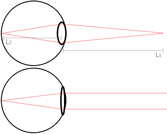
A simplified and exaggerated schematic of the eye focusing on objects at near and far distances, by changing the curvature of the lens. Again rays should be interpreted as tracing wavefront normals. A physiologically correct model of the eye might use as many as four aspheric lens elements, to account for the different surfaces and fluids inside the eye. For the purposes of this discussion, all these effects are drawn as one lens element which achieves the combined wavefront curvature modification.
A lens introduces aberrations when its action on an incoming spherical wavefront does not result in a spherical outgoing wavefront. Generally the flatter the lens, the lower the curvature shift, and the smaller the aberrations. Hence the eye with the pupil contracted, as in bright lighting, will see a sharper image than the eye with the pupil dilated, as in dim lighting. A very narrow pupil also makes the eye more like a pinhole camera, and there is an associated increase in depth of field (the range of object distances which can be in focus at the same time). These considerations apply in photography as well, with the main difference being that changing the lens curvature is done by changing the lens altogether, and objects are brought into focus by moving the lens axially thus changing L2. With photography lenses, the limitations of the "focal length" terminology become straining, as it may well be the case that no physically meaningful distances in a camera system correspond to this "length".
With the ability to change the curvature of the lens in the eye, a typical eye can bring objects to a focus with L1 ranging from about 20 cm (hand held in front of face) to infinity (stars in the sky). Hence, when we design optical instruments to be used with the eye, we should design them so that their emitted wavefront reaching the eye matches the curvature of a wavefront that would have been emitted at such L1. Further, the eye pupil diameter of approximately 6 mm sets the maximal aperture of the system, and a well designed instrument will have the limiting aperture slightly in excess of this (so as to not be unnecessarily large nor too small). Higher apertures are often useful, in which case a camera or another detector will need to be used instead of the eye. On the other hand, if we want a camera to capture an image similar to what the eye sees, no more than a 6 mm aperture is necessary, and even smaller sensors appear in modern cell phone cameras, reaching the informational limit of the field with 1 mm lens diameter (with these advances in lens and sensor design, the carrying around of large bulky cameras will be increasingly relegated to hobby status much like vinyl records in the audio realm).
The magnifying glass is a simple refractive instrument, yet its usefulness comes from the combination of its action with the eye, hence a 2-lens system is formed. Most introductory treatments hastily skip over how this instrument works, so I will try to give a more comprehensive coverage here. Because the eye is included in the system, there are now two constants - the retina-lens distance in the eye and the curvature shift (focal length) of the magnifying glass; there are also three variables - curvature of the eye lens, distance from eye to magnifying glass, and distance from magnifying glass to object of interest. Changing the variables can result in different regimes: two imaging modes - [M1] upright (non-inverted) magnification and [M2] inverted de-magnification, and two non-imaging modes - [M3] curvature above eye accomodation (object too close to eye to focus) and [M4] curvature below eye accomodation (virtual image with negative curvature entering eye). Which of the four modes will be observed will depend on how the variables relate to the constants mentioned above. Nonetheless it should be acknowledged that the magnifying glass does not "pick" a mode to operate in; rather all modes are intrinsic in how the curvature shift of the magnifying glass affects the incoming wavefront, and which one we "see" depends on how we observe and interpret the outgoing wavefront. Some abbreviations will be useful: MG for magnifying glass, MGF for MG focal length, EL for eye lens, ELF for EL focal length, O for object that is imaged. The non-imaging modes are easy to define: in [M3] O is closer to EL than the minimum of ELF and MGF; in [M4] O is further than MGF from MG while MG is closer than ELF+MGF to EL. In [M3] and [M4] everything through the magnifying glass looks like a blur, so we will not treat them further here.

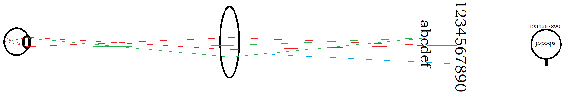
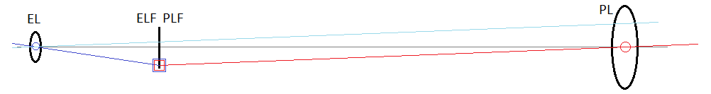
The diagrams represent [M1] imaging with the magnifying glass, with the eye close to MG in upper, and far from MG in lower. The positions of the eye and object along with rays shown on left, and what the scene looks like to the eye shown on right. The letters are taken to be under the MG, while the numbers are on the same plane but outside the MG, to give context to what size the letters would appear if not looking through the MG. Note the size of the letters "cd" through the MG is the same fraction of the visual field in both cases, but the apparent magnification (comparing the letters to the numbers) becomes higher when eye is far from MG. Also, with EL far from MG, the green rays that enter EL must travel through outer (more curved) radii of the MG, which will increase aberrations at the image edges.
[M1] is what is typically imagined when thinking of using a magnifying glass - here O is within MGF of MG, and probably near MGF for apparent magnification. In simpler language, the magnifying glass is held within some 15 cm of the object that needs to be magnified, and the eye may look at the magnifying glass from near or far. Because the curvature shift of the MG is constant, placing the MG very close to O (where the emitted wavefront curvature is high) has little effect, while placing the MG near MGF away from O (where the emitted wavefront curvature is lower) has a notable effect. It is interesting to consider what peak magnification may be achieved, and why. The unaided eye can focus on objects about 20 cm away from the face, and the magnifying glass typically has a focal length of some 15 cm, so let's say ELF = 20 cm, MGF = 15 cm. Angular magnification comes from the combined effect of curvature shift, here the ratio ELF/MGF = 1.33x, which is not very impressive. However if ELF is 100 cm, then ELF/MGF = 6.67x. That is to say, the closer near your face that you can view an object with the unaided eye, the less useful a magnifying glass is to you. With age, the muscles in the eye are less able to achieve a low ELF, hence we are more likely to see elderly people carrying around magnifying glasses, while younger people simply bring the object closer to the face and achieve the same effect. Also, if for some reason it is not possible to bring an object closer to one's face, such as from difficulty of motion or the object being inaccessible, then bringing a magnifying glass near the object will result in an apparent magnification, acting as if the eye were teleported forward to where the MG is held. So indeed, for objects that are a hand's reach away, bringing the MG within MGF of the object will cause a section of the object to appear definitely magnified to the eye. However, then bringing the eye closer to MG, one will observe that the visual size of the "magnified" object in the MG stays the same! And at very close range, near minimum ELF, the "magnified" object will look barely bigger than if seen without the MG. So the apparent magnification of a MG, for young people at least, is more due to the objects outside the MG appearing smaller from further away, than it is due to the objects within the MG appearing larger (although a modest true magnification on the order of 1.33x does happen). A loupe is a particular subclass of magnifying glass that has MGF on the order of 2 cm, or corresponingly a higher curvature shift (and smaller diameter). The higher curvature shift makes a low-aberration lens design more complex, so the loupe will have two or more, possibly aspheric, lens elements in series. However, because even a healthy eye cannot reach such short ELF, the loupe can make visible features that would have been indiscriminable otherwise, with angular magnification of some 10x. The loupe is thus a sort of middle-ground between the unaided eye and the microscope, and we will re-visit it below in the microscope study.
The diagram represents [M2] imaging with the magnifying glass. In this mode, the letters appear inverted and possibly de-magnified compared to the numbers outside the MG. An image plane exists in front of the MG, which is where the inverted letters appear to float.
Another imaging mode that can be achieved with the MG is [M2], where the object appears inverted as it is further than MGF from MG, and the eye can focus on an image plane that will exist between MG and EL. In simpler language again, [M2] may be entered by holding a typical magnifying glass at an arm's length, and looking at distant objects. Physically, the division between [M1] and [M2] is arbitrary - the transition in wavefront curvature is a continuous one, however our interpretation of what is seen takes on this binary character. This mode is not particularly useful with a magnifying glass, but it demonstrates how the formation of an image plane causes an inversion, and we can gain insight from this when we consider it below in the context of the telescope.
For mechanically inclined readers, the magnification and field of view in an optical system will perhaps be more understandable if presented with a lever-linkage analog model. To draw this model, begin with the lenses at their to-scale locations and sizes, and place a pivot point in the center of each lens. Next, draw a vertical line at each lens's focal plane, or wherever an image is actually or apparently formed. Finally, draw straight "lever" lines through each of the pivot points, and connect these lines with "linkages" at the vertical lines. (For a focal plane "at infinity", the linkage causes the linked lines to be parallel.) To intuit how the input and output optical rays behave, imagine pressing on one of the line ends so the lever rotates around the pivot point, and then acts on other lines at their intersection points, much like two-lever bolt cutters are designed to amplify force, or mechanical indicators are designed to amplify displacement. Such diagrams are presented below for [M1] and [M2]. For [M1], note that while the object under the magnifying glass appears bigger than it would to the naked eye (dark blue vs faint blue lines), the angle of the blue line is actually lower than that of the red line, hence one might say that no angular magnification takes place! For [M2], the object through the magnifying glass is smaller and inverted compared to what is seen with the naked eye.
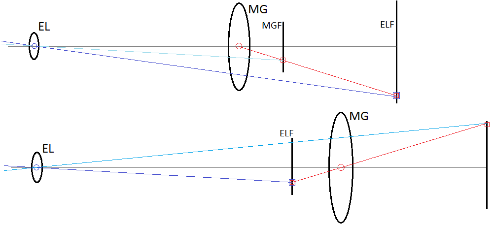
A mechanical lever-linkage model of the eye looking through a magnifying glass. Upper diagram represents [M1], lower [M2]. The red and blue lines rotate around the red and blue pivots respectively at the centers of MG and EL. They intersect at the blue+red square marked point in ELF which may move vertically. Imagine the change in blue line angle as the red square is moved up and down along the imaged object, and compare to the faint blue line representing what is seen without MG.
The telescope is an instrument intended to make distant objects appear bigger to the eye. In particular, with primary lens PL and its focal length PLF, distant means more than 2x PLF away from PL, and typically so much more that we can assume the incoming wavefront incident on PL is flat. This situation is in principle not so different from [M2] with the magnifying glass above. When this occurs, because the nearer image plane is between the PL and EL, the resulting magnification is also inverted: unlike ELF/MGF for the magnifying glass in [M1], we have PLF/ELF for this [M2] analogue. Looking through a magnifying glass in [M2] at the stars, one will see a de-magnified image because MGF will be the shorter distance, which is not very useful. Instead, we want PLF to be large so we achieve magnification in this mode. This makes a class of telescopes that may be called the "one-lens telescope", where the lens of the eye acts as the second lens to magnify an inverted image formed at ELF away from EL. The challenge for this type of instrument is the size of elements required. For instance, to achieve a magnification of 30x, PLF = 30*ELF or PLF = 6 m. The PL would need to be placed over 6 m away from the eye, and for a modest field of view (about the length of the thumb on an outstretched hand - 5 cm at 1 m) would need to be at least 30 cm in diameter (PLD). At this rate, the PL should be fixed in a stationary mount and the observer walk far enough away from it to make the observations, and such an approach was taken in early tubeless "aerial telescopes" (however, as far as I can tell, these were used with a second eyepiece lens - we cover why below).
A mechanical lever-linkage model for the one-lens telescope. This is basically the above [M2] diagram, but with the linkage plane closer to EL than to PL, thus achieving angular magnification. The faint blue line is drawn parallel to the red line as what would be seen with the naked eye (sharing a linkage point at a very distant plane), to make the magnification clearer.
The above diagram is slightly misleading because I did not draw the lenses to scale (otherwise the magnification would be difficult to see). If drawn to scale, it will be apparent that the field of view is very limited when PL is placed far away from the eye, because properly the extension of the red line should be inside the eye pupil for that point in the image plane to be visible at all; taking the diagram literally, the blue+red square would not be able to magically redirect the red ray towards the eye so the eye would see whatever is outside the lens instead of the image formed by the lens. (One might imagine that a "field lens" placed in that location could redirect the rays and enhance the field of view, which was actually done.) But it seems we have gotten too entranced by the rays and levers, and forgotten about the field nature of light! Because while rays demonstrate the field of view limitation, a more substantial issue is the diffraction limit as we saw in the pinhole camera study, because a tiny lens that is very far away begins to look to the observer like the aperture of a pinhole camera seen from the inside. With a small PLD and large PLF, the reduced field of view combines with diffraction to worsen the image resolution. (The optical concept of numerical aperture relates roughly to PLD/PLF, and appears in the Abbe diffraction limit.) We found in the pinhole camera study that the first interference fringe occurs at θ≈2.44*λ/d, and from the point of view of the observer, to resolve 1000 "pixels" in the image formed by the PL, we need to resolve θ≈(d/L)/1000. Equating the two gives d2/L=2440*λ, or for PLF=60 m, PLD=27 cm. This represents the approximate limit of useable PLF with the aerial telescope, which is confirmed in the historical record.
We can enhance the field of view, reduce PLD and PLF, and improve the diffraction limit, by using a secondary lens SL with short focal length SLF. If we decrease from ELF = 20 cm to SLF = 1 cm, for instance, then for 30x magnification, PLF = 30 cm. This is easily achieved within the size of a pair of binoculars, indeed we can use a large relative PLD for a correspondingly wider field of view. Because the diffraction limit improves as PLD2/PLF, reducing the PLF while maintaining large PLD will increase the maximum resolution of the instrument. The brightness of the observed objects will also improve if the small PLD was setting the aperture on the system, which is not a major factor for astronomy (looking at bright stars in the middle of the night), but can make a big difference for observing terrestrial objects. In all, there are many advantages to be gained by reducing the focal lengths of the lenses in the telescope system. The main disadvantage is that a short focal length requires a high curvature shift, which more easily introduces aberrations. Thus aerial telescopes were in use until low-aberration lens shapes for high curvature shift were developed.
So, we can make a telescope with secondary lens SL, such that PLF/SLF gives a high magnification. ELF is removed from the equation altogether - the eye sees a flat wavefront where the difference in wavefront normal vector from the optical axis has been magnified by the telescope. This instrument is the Keplerian telescope, which may be also thought of as using a loupe to observe the tiny details of an image formed by the primary lens. The observed object, however, appears inverted. If we use a concave (diverging) SL, we will have the Galilean telescope, where the magnified object appears upright.
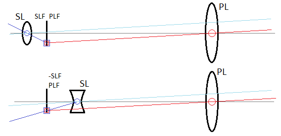
A mechanical lever-linkage model for the two-lens telescope. Upper diagram is Keplerian (converging-converging), while lower is Galilean (converging-diverging). Both can have the same angular magnification as illustrated here, but the Keplerian forms an inverted image and has improved field of view.
Having an inverted image makes it more difficult to point the telescope towards the object of interest, and to observe the object especially if it is terrestrial. Thus for terrestrial uses the diverging eyepiece would be preferred, with an additional advantage of a shorter overall microscope length. However in most binoculars and similar optics today, the converging eyepiece is used along with a prism to doubly-reflect the rays so that an upright image is seen. The reason for this is an improved field of view with the converging eyepiece. Because the diverging lens diverges the incoming wavefront, seeing the entirety of the wavefront requires a pupil larger than the lens itself. Practically, when using a Galilean telescope, the complete field of view will be explored by moving the eye laterally relative to the eyepiece while keeping the telescope still. With the Keplerian telescope, there is no need to do this because the wavefront is converging towards the pupil.
A schematic ray trace for the two-lens telescope with converging and diverging eyepiece, and what might be seen through the eyepiece. This illustrates why the latter has a reduced field of view: the blue rays for the object further from the optical axis separate further after exiting the eyepiece and do not pass the green aperture representing the eye pupil, while with a converging eyepiece the blue rays are redirected back towards the axis after exiting the eyepiece and pass the green aperture. Rays between these angles will partially pass through the pupil in the diverging eyepiece, resulting in vignetting. Moving the eye relative to the diverging lens in the opposite direction of where the object appears (gray circle) can be used to cover the same view as in the analogous converging case.
From the other side of the telescope, it may be used to send out light towards a target, for instance to send a laser beam to the moon and calculate its distance from the earth based on the roundtrip wavefront propagation time. Here again diffraction and the field nature of light must be considered. Playing with a handheld laser pointer, one may wonder whether the spot size of the laser beam on a distant object will be the same diameter as it is nearby. Actually we already analyzed this situation with the pinhole camera, S≅d+2.44*λ*L/d, where the laser beam diameter coming out of the laser pointer is the diameter d of the "pinhole" while S is the spot size of the laser beam on an object at distance L from the laser pointer. Counterintuitively to what rays would suggest, a larger diameter laser beam will have a lower divergence angle, so its spot size on a distant target will be smaller than that of a small diameter laser beam. This is because in the field, a larger diameter means a more precise definition of angular propagation direction. If the laser beam is sent through the telescope from the eyepiece into the primary lens, its diameter will be expanded by the magnification factor, and its divergence will be reduced by the same factor. For large L, the (1/d) term has the primary contribution to S, thus making a large diameter beam is always preferred. In the real measurements with lunar laser ranging, the laser beam is expanded through a large diameter telescope so its diameter leaving the observatory is as large as possible; subsequent measurement of the returning laser beam is done through the same large diameter telescope (taking into account that it will be returning at a different angle since the moon is moving relative to the telescope). At the Apache Point Observatory, the laser beam (λ = 532 nm) is expanded to d = 3.5 m, and with the moon at L = 380000 km, S = 144 m (in actuality about 10x bigger due to atmospheric turbulence). If the laser were not expanded but instead sent out with d = 9 mm, then S = 54.8 km (and more with turbulence), with an associated reduction in incident power per lunar surface area.
Whereas the telescope makes distant objects look bigger, the microscope makes nearby objects look bigger, where nearby is defined as approximately at PLF away from PL. In this sense, it is similar to the magnifying glass or loupe in [M1]. A single lens will be used for approximately 10x magnification, while higher magnification will require using two lenses, so using a loupe to magnify the image made by another loupe. The diagram would be similar to the telescope but with the imaged object at PLF instead of at infinity. As with the telescope, the image will be inverted, so most modern microscopes have a prism or mirrors in the optical path to form an upright image seen by the eye. The main challenge in designing a microscope is manufacturing low aberration and high curvature shift lenses, on which entire textbooks are written, so all I will say is that multiple converging and diverging lenses are typically used in series to achieve the performance of a single "ideal" lens. (A point to consider with multiple lenses is that uncoated glass will reflect some of the incident light, causing strange "ghost" images, stray light, and reduced primary image brightness; anti-reflection coatings serve as an "impedance match" between the wavefront in free space and the wavefront in the lens, and are practically a must in multi-lens systems.)
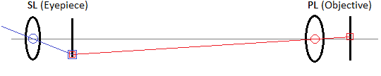
A lever-linkage diagram for the two-lens microscope.
Unlike the telescope, in a microscope the source of illumination must be designed with the instrument, because this source can enhance image contrast and because the PL must be close to the object where it blocks out possible external illumination. This gives another possibility where the aperture is limited by the illumination source instead of by the magnifying path. As mentioned before, a system of lenses does not affect the observed brightness of an object, so one may ask why illumination is such a concern - just put a lamp somewhere behind a transparent sample or in front of a reflective sample. Here I will consider transparent samples illuminated from the back, as done in biological applications, but the same treatment applies to reflective samples illuminated from the front. If a lamp is placed behind the transparent sample, the wavefront reaching the sample will have a particular directionality because the distance between the lamp and the sample limits the spherical emitted wavefront to a particular cone through it that is along the optical axis. The unchanged brightness statement applies to uniform emitters, that is ones emitting a spherical wavefront, and when we have a sample illuminated by a directional emitter, the resulting wavefront is not spherical, so the brightness may be reduced with increased magnification. In this case the illumination sets the aperture. Consider: if the brightness of the image stays constant as magnification increases, this means a larger area of the image is filled with light from the same area of the object, which requires more energy, and where does this energy come from? It comes from capturing a greater solid angle of the spherical wavefront emitted by the object, up to the practical limit of half of the spherical shell when the sensing element is all around the emitter surface (as may be achieved in oil immersion microscopy). If the object emits light uniformly, then we capture a smaller cone of the emitted wavefront at lower magnification, and a bigger cone at higher magnification, so more of the emitted energy (from a smaller area) makes it through to the image as we increase magnification. However if the object emits light with a particular directionality, then increasing the captured cone does not necessarily increase the amount of energy reaching the image, so a decrease in brightness is observed if the image area is also increased. By analogous reasoning, the diffraction limit on image resolution is worsened. (This is, of course, true of the telescope as well - if we try to get high magnification with small lenses, the image brightness will decrease, because the small lenses capture a relatively smaller fraction of the incident wavefront. To maintain the same brightness as seen by the naked eye, the PLD should be larger than the eye pupil by the magnification factor.)
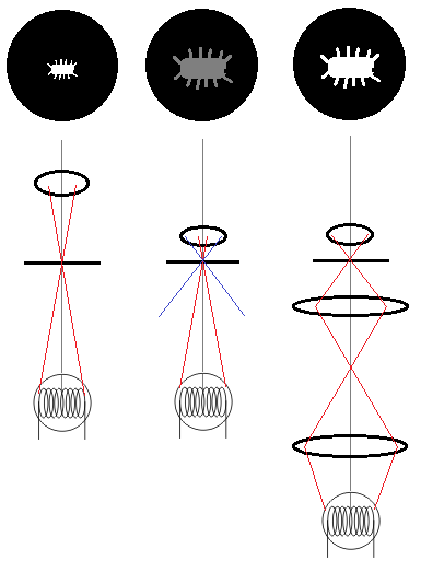
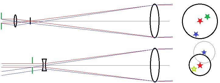
A ray trace for the illumination light in a microscope along with a sample of what might be seen through the eyepiece. On left, a low magnification lens might be adequately illuminated by a light bulb filament. In middle, the light from the filament at the sample does not have a large enough cone to fill the capability of the lens (red vs blue lines), and thus the image is larger but dimmer. The effect is the same as if we put an aperture in the magnification path. On right, two lenses are used to increase the dispersion of the defocused light, resulting in a return to the original object brightness.
A simple remedy would be to place a uniformly emitting surface behind the transparent sample. This was done in early microscopy by using skylight. However, this technique is quite wasteful of light because most of the light emitted by the surface will not make it to the sample and objective lens, so with an artificial light source the image is likely to be dim. Improved efficiency may be achieved by using a lens to focus incoming light, which increases its cone of incidence as seen from the sample. In this case, an image of the light source is formed at the sample, so the light source itself should be featureless, such as the bright section of a flame plume. To use a more convenient source like a light bulb filament, it is necessary to increase the cone of incidence on the sample while also defocusing the image of the source at the sample. This is achieved in Kohler illumination, by using a second lens to defocus the image of the light source while keeping it pointed at the sample (along with some diaphragms to adjust angles of incidence). The two lenses (diaphragm and condenser) in a way make a converging-converging telescope pointed at the light source, with the magnification of this telescope causing increased divergence of the unfocused incoming light at the sample plane. These lenses can be simple spherical ones, because they are not used for imaging and aberrations are not important.