Xenon Strobe Light
November 21, 2011
Idea
This project came about as a natural evolutionary step after the LED Strobe Light. It is much more powerful, running at 240VDC, and is an actual strobe light in that the flash is nearly instantaneous (whereas with the LED model the flash is not nearly as bright and has a relatively longer duration). However, as a consequence of the higher power output flash frequency had to be sacrificed (otherwise the flash bulb and capacitors overheat and get damaged), so this circuit does not allow speeds much in excess of 8Hz or so, whereas the LED model could go above 100Hz. Note that to dissipate heat most of the components were mounted about 1/8 to 1/4 of an inch off the board to allow convection cooling.
Warning
This project uses 120VAC from mains power, so an insulated case is necessary, along with a fuse and power resistor. Do not build unless you understand electronics and have experience with high voltage and AC power.
Circuit
The circuit I designed was from a kit at electronic goldmine. I know, putting together a kit is not much of an original project, but this time it was much more convenient since I understood the theory behind the circuit and buying the kit provided me with all the necessary components and a neat circuit board to put them on. Otherwise it might have been quite messy, and I did not feel like searching through the components I had lying around (although I know I did not have the right type of capacitor for this circuit).
This runs off 120VAC, which goes through a rectifier and a voltage doubler to create 240V+ that is stored in capacitors. A resistor in series with a neon bulb (which conducts at around 200VDC) serves as an automatic trigger that fires when a certain capacitor voltage is reached. Since a higher voltage corresponds to a longer charging time, a variable resistor here would effectively control the flash rate. Once the neon 'relaxation oscillator' triggers, it is known that around 200V are stored in the capacitors, which is necessary to create the flash. This trigger goes through an SCR which allows the 200V to go through a transformer that ionizes the gas inside the Xenon flash tube. This ionized gas, in turn, provides a low-resistance path for the rest of the charge stored in the capacitors which discharge their energy through the tube creating light in the process. Once the voltage supplied to the tube drops to about 50V, the current through the gas can no longer be sustained and the tube acts as an open switch. Then the charging cycle starts over again.
[Circuit Diagram TBA]
Photos
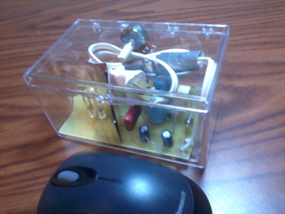
This image is the completed project, in a nice transparent box also from goldmine. It actually adds a nice touch, being able to see the circuitry while having it protected, and self-contained (the wire fits inside the box nicely). The mouse makes another appearance for size comparison.
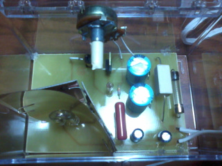
Top view, where the speed control potentiometer (with tape added to the handle for some added insulation) as well as the rest of the circuit is visible: xenon bulb and reflector in bottom left, then four round capacitors and the red capacitor, a power resistor and the fuse right next to it. The transformer, resistor, neon bulb, and SCR are under the potentiometer. There are also two diodes that make up the rectifier/voltage doubler, which are behind the two big capacitors. That is the extent of the circuit.
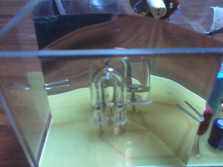
A closer view of the flash tube and reflector. It is a horseshoe-type tube.