The Vernier principle is the design of an interference pattern between N and N-1 (or N+1) elements arranged evenly in an identical length, such that the matching part of the pattern appears to complete an entire cycle length when the N pattern is shifted by 1 step. This is very similar to the appearance of a beat frequency fb = f1-f2 when two waves of frequencies f1 and f2 are combined. There is an interesting number theory proof to be found here, that two adjacent integers are always coprime; for other combinations like M=N-2 the highest visual ratio is P:N where P is the highest common factor of N and M, and the apparent interference will be repeated P times within the length of the pattern. The phenomenon can be seen as a type of visual harmonic gearing, which provides a high ratio (namely N:1) of apparent turns to actual turns. As such, it is commonly found on precision measuring devices - in particular calipers and micro-meters, where it can give a direct human-readable indication of movements that would be too small to easily sense otherwise. On calipers, the N pattern is the movable piece, and the ruler has an N-1 pattern so that the visual indication moves to the right when the movable piece is shifted to the right. On micro-meters, it is the same situation - the N pattern is the rotating knob, and the stationary piece again has an N-1 pattern so that the visual indication rotates clockwise when the knob rotates clockwise. Can this be applied to clocks? A clock based on this approach could have just one moving hand, the hour hand, and the minute and second hands would be visually generated by the faster apparent speed of the interference pattern as the hour hand moves.
For a traditional clock, the minute hand makes a full revolution for every 1/12 of the hour hand revolution, and the second hand makes 60 revolutions for each minute hand revolution. Again the moving part will have N elements, and the stationary part N-1, such that the visual rotation direction matches the mechanical rotation direction. Using N+1 elements instead of N-1 on the stator will mean that the apparent visual rotation will be backwards - it will move counter-clockwise 1 revolution for each clockwise 1/12 mechanical revolution. The required visual ratios are thus 12 and 720, and making the visual patterns will require 12 and 720 elements. The 12 elements is easy to do, but 720 poses challenges. Consider the clock is 30 cm in diameter, which is a 942 mm circumference, which means each of the 720 patterns must take 1.308 mm, and if the patterns are half-filled then the line thickness must be 0.654167 mm. However the N-1 pattern will have 719 elements, having the line thickness of 0.655076 mm. The difference between the two thicknesses is 0.000909 mm, that is 909 nanometers. The 720 and 719 elements can be printed, but the interference will not be very good, and pixelation artifacts will be apparent. Getting this many elements would require lithographic techniques, and even then there would be another major challenge of getting them lined up properly (again within 1 micrometer).
Thus I came up with a few modifications. I could use a 24 hour clock, which gives a ratio of 24 on the minute hand. Then I could again use the ratio of 24 for the second hand, meaning this hand would make a visual revolution every 2.5 minutes. This gives the ratios of 24 and 576, where the 576 will still be a challenge but not as bad as 720. Next the elements are designed so that the two patterns are on overlaid disks, and there are gaps in the disks such that when the two disks are aligned light can pass through the gaps and be visible to the observer, while when the two discs are aligned differently the gaps are blocked and a dark area is seen. This has the purpose of a visual "amplification" of the signal, because an imbalance in dark area fraction or "heaviness" of image is easily perceived at a glance.
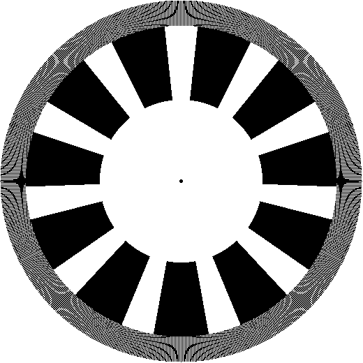
To test out the performance of different elements, I wrote a scilab script (download here) that would draw the elements at different rotations of the hour hand to represent the appearance of the clock. A GIF combining script (download here) is then used to compile an animated GIF of what the clock would look like. These scripts require the Scilab Image Processing and AnimaGIF toolboxes to be installed. The following images show the patterns for the stator and rotor elements, and what they look like when they are overlaid and the rotor elements are rotated. The black parts represent mechanical blocking of the light behind the pattern, so when two are overlaid the slots of one pattern can cover the gaps in the other pattern. The ratio of this pattern set is 12, so if the inner circle is taken as the hour hand, the outer circle can be taken as the minute hand. As expected, the outer circle makes one visual revolution for each actual 1/12 revolution of the rotor pattern. The minute readout is not very precise, but can be ascertained to within 5 minutes from the appearance of the interference.


On left is the stator or base of the clock, and on right is the rotor connected to the hour hand. The slots and gaps overlap and create the appearance of a dark area that moves faster than the mechanical rotation of the rotor.

Rendering of a complete revolution of the rotor pattern overlaid on the stator, representing 12 hours, during which 12 revolutions of the interference patterns take place.
Having some parameters for the stator and rotor patterns, it is now necessary to create files that can be used to machine these parts. The easiest approach here will be to use a standard printer, print the patterns on transparency film, and then affix the transparency film onto thicker plastic discs. For this, the necessary files would be images at a sufficiently high DPI. Another scilab script (download here) is written to generate the patterns and write them to a large BMP image. This takes a lot of time and memory, because each pixel is stored as an integer although it only requires one bit because the image is black and white. Going element by element leads to significant aliasing when trying to draw the thin lines and sections correctly, so instead I use a pseudo ray tracing approach - each pixel in the image is tested for whether it's in an area that's meant to be filled, and if it is, then the pixel is filled. This provides a nearly constant runtime even for the thousands of elements required at high ratios, however this constant runtime is quite long because as the image gets larger, so does the number of pixels to test. Some example images of the stator and rotor, for the standard ratios of 12 and 720, rendered in a 520x520 pixel size, are included below.

Stator and rotor with ratios of 12 and 720, rendered on 520x520 pixels (click image for full resolution).
I had intended to build a working clock, with the main mechanism taken from an old 24-hour timer using a synchronous motor. However with everything shut down due to covid, I don't have access to an adequate machine shop to do this properly. The biggest challenge, and one I did not sufficiently appreciate until the patterns were printed, is aligning the patterns precisely enough in the radial direction - because the ratio for the second hand is so large, even a tiny offset misalignment of the patterns when their center points are not exactly overlaid, probably to within a few micrometers, throws off the interference completely and the outer second disk looks like a messy pixelated blur. This effect can be seen in the video below. Thus having such a high ratio in a practical clock necessitates both a rigid rotation mechanism that won't wonder off center or wobble, and a means to precisely align the discs during and probably after assembly. However it seems that when aligned just right, the interference does work as expected, moving at the correct ratio and appearing much like the rendered GIF above. Overall the Vernier clock is an interesting concept, though to anyone wishing to make a similar device, I would recommend finding some creative way to greatly reduce the second hand ratio to something around 100, which will simplify both fabrication and assembly. The Vernier pattern could definitely be attached to a regular minute hand with a ratio of 60, providing an eye-catching visual rotation every minute while keeping the standard appearance of the hour and minute hand for normal time reading.
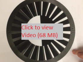
A video of the interference pattern that the actual printout generates. Here I am rotating the stator transparency, so I am turning it counter-clockwise which makes the pattern move clockwise. The ratios here are 24 and 576 for a 24-hour clock, so this looks different from the above renderings.