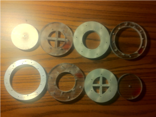
The 8 circles mentioned above are seen in this photo. They were cut out from a 12x5x0.5in aluminum stock and same size plastic stock, using a waterjet cutter. The biggest circle diameter is 4 inches, to match the stacked height.
The Evil Twin sphere had some nice digital circuitry and functioned relatively well, however eventually it succumbed to physical wear. After all, a carved-out ball of styrofoam really can't stand up to much use as an object meant to be thrown around, even though I painstakingly applied a two-part plastic epoxy to the surface to hopefully protect it. The main issues with the Evil Twin were attaching the outside aluminum foil to wires to connect them to the high voltage transformer (since aluminum cannot be soldered to anything) and keeping the ball together since it was split into two halves that had a tendency to fall apart. There was a noticeable gap between the two halves, and with use this worsened to the point that one half would slip off and the ball would not be of any use at all. So the project was given up, a year passed, and then inspiration struck me. In this year I learned a lot about machining and construction, and came up with a way to make a structurally stable hollow sphere with metal contacts integrated into it. It was an interesting challenge. Now it was clearly time for the revenge of the power sphere, with completely new solid-state construction and circuitry.
How does one make a hollow sphere? The way I came up with was to cut out circles of 0.5in thick aluminum and plastic, with properly calculated radius, and subsequently put the assembly in a lathe and cut it into the shape of a sphere. The sphere would be 4in thick, and thus comprised of 4 circles of aluminum and 4 circles of plastic stacked on top of each other, so that aluminum circles are insulated and the shock is created by applying a voltage to the aluminum circles. Additionally this design is symmetric and thus more aesthetically pleasing. Perhaps it can be better understood through photos:
The 8 circles mentioned above are seen in this photo. They were cut out from a 12x5x0.5in aluminum stock and same size plastic stock, using a waterjet cutter. The biggest circle diameter is 4 inches, to match the stacked height.
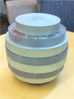
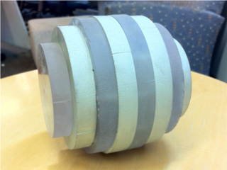
The circles from above have now been stacked and bolted together. The shape doesn't really resemble a sphere, but it will be evident after some work on the lathe.
I chose 4in for the diameter because it seemed like a reasonable size for holding in one hand (it is) and it would allow for an adequate amount of internal space for the circuit (just barely). The circles shown above are entirely symmetric between plastic and aluminum. They are bolted together in this fashion: each of the middle (largest) circles attaches to the other one (6 bolts total), then from the middle the smaller size circles are bolted to either side (6 bolts per additional circle), finally ending with the end cap attached by one bolt. Only two bolts are visible from the outside - one on either end cap. That is why the space inside the sphere is not as large as may be thought - for the bolts to be hidden from the outside (for aesthetic reasons) the inner diameter of each circle needs to be less than the minimum outer diameter of the next smaller circle.
There are 6 bolts attaching each circle to the next one, which may seem excessive but it is justified because the bolts are 0.067 inches in diameter, and the whole assembly needs to be able to withstand the shear power that would be applied by the lathe cutting action. The 6-bolt attachments held up well in the lathe, however the end caps were a problem. I mentioned already that they were attached by only one bolt, however this would be useless for lathing because the end cap would just spin around the bolt. In order to counter this I designed the circles immediately following the end caps with the cross-shape in the middle, so that 4 internal pins are placed on each leg of the 'x', and corresponding holes in the end cap prevent it from spinning about the center axis. This provides adequate shear resistance to be used in the lathe. However the pins do not prevent the end cap from traveling along the axis of rotation - that is left up to the single bolt. This worked fine for the plastic end piece attached to aluminum, since plastic is easy to cut and aluminum threads held the bolt well, however for the aluminum end cap attached to plastic there were significant problems. When the aluminum end cap was being cut in the lathe, the bolt attaching it to the plastic disk stripped the plastic threads easily, which allowed the aluminum piece to travel along the axis and into the cutter on the lathe. Obviously this caused a huge load on the cutter, and resulted in the entire end cap shearing from the plastic disk, breaking the four pins which were meant to prevent it from rotating. Luckily I saved the parts from the waterjet cutter that were cut out to make the 'x' shape, so I was able to epoxy those back in and obtain a solid plastic disk instead of the hollow x in the middle. This gave me a second chance at machining without having to redo the parts. But at the time I did not realize the problem was due to the bolt, not the four pins, so the same incident happened again. This time the four pins fell out instead of shearing, so the plastic disk was still usable. I found a bull-nose center to use on the lathe, in order to apply pressure to the aluminum end cap, to prevent it from traveling along the axis of rotation since the bolt would provide no support due to the stripped plastic threads. This approach worked well and allowed me to finish the job. So I guess the lesson is to plan how well the part will stand up to being machined, and to consider the hardness of materials, especially machining aluminum attached to plastic. The entire process of lathing took two days to finish, and involved about 80 cutting passes (0.05 inches per pass, 4 inches total) and some scrambling to keep the aluminum end from falling off. The results however were worthwhile:
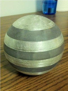
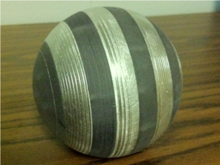
The stacked disks from above have now been lathed to a 4-inch diameter sphere shape!
Electronics time! After using the basic stamp microcontroller in the Evil Twin, I wanted to have the benefits of a digital accelerometer in the shock circuit. The spring-based system of the Original Sphere would not work well here, because the ball is so heavy that it would take conscious effort to accelerate it enough so that springs can create a shock, unless the springs are made extremely sensitive, and in that case they would likely break with regular use. The accelerometer on the other hand is able to respond to slight changes in force, so no matter how 'smoothly' one catches the thrown ball, they will get a shock. However, the basic stamp was used in another project (Lightning Reaction) and in any case was too big for the space inside the sphere, and with such a simple program it was really not elegant having a whole microcontroller in the sphere. The same thing could be accomplished much more efficiently using a custom circuit.
Reviewing the Evil Twin circuit, I found that the accelerometer has a very useful free-fall output which is a logic signal that can be easily used by analog circuitry. The challenge was that the shock needs to occur after freefall ends, not during freefall. To accomplish this I used a SPDT relay that would charge a capacitor when the relay is closed (during freefall), and discharge the capacitor when the relay is open (not in freefall). This is RLY1 in the circuit diagram. The capacitor is discharged through a transistor that activates another relay (RLY2) which enables the high-voltage generator and creates the shock. Once the capacitor discharges, RLY2 is opened and the shock does not occur until the next freefall causes the capacitor to charge again.
The actual circuit was designed so that the maximum shock time is quite short, so the shock is noticeable but not painful, and additionally there is a short time delay between catching the ball and the shock occurring, which would allow throwing the ball quickly without getting shocked (a hot potato type game). Also the longer the ball remains in free-fall the longer the shock will be, up to the maximum shock length. Finally there is a filter that ignores sporadic freefall pulses, which may occur when lowering the ball to the ground while holding it, thus no shock is produced unless the ball is actually thrown. All of these factors, along with protecting transistors and the accelerometer from undesirable electrical conditions, have made the circuit slightly more complicated in terms of added capacitors and resistors, however it would not be usable without them. Note that the driving voltage for Q1 is 5V while 9V is required for the relay to activate, so the relay must be on the collector side of the NPN transistor (ie not the arrow side)! If it is on the emitter side, it will only have 5V applied due to weird transistor voodoo magic.
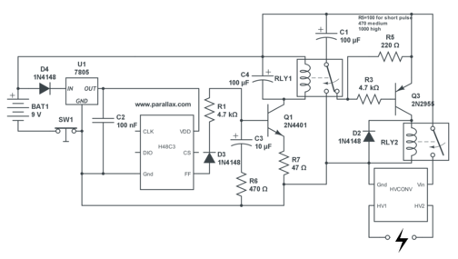
The circuit diagram for the newly designed sphere, which keeps the advantage of a digital accelerometer while introducing features that would be necessary for practical use of the sphere.
I have been asked how the high voltage is generated - this particular design uses the 'RCD' shock generator as described on the shock page. Essentially it suddenly breaks the current flow through an inductor (high voltage transformer primary) using a mechanical relay, thus causing a large voltage spike in the transformer secondary.
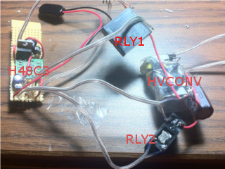
A photo of the constructed circuit, with the accelerometer, shock generator, and two relays labeled. All the small components (capacitors, resistors) are on the breadboard along with the accelerometer. A 9V battery connector is visible, along with the wires that connect all the large components, so they can be easily maneuvered within the sphere.
The final part of the race was to get the electronic circuit inside the sphere. This proved to be more of a challenge than I imagined, since the 9V battery took up about a third of the usable space, and I had to ensure the shock wires remained connected to the aluminum disks of the sphere, insulated from each other, not affected by the position of the components inside the sphere, and additionally that the turn-off switch would be functional. The sphere is assembled from the middle out, so there are two access points to the electronics until the end caps are placed on.
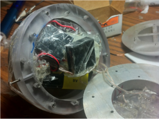
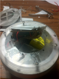
The two relays are on the 'bottom' side of the sphere as it is being assembled. They are all taped to minimize the chance of a short-circuit. Wires are visible leading to the metal disk on the right, these wires deliver the high voltage for the shock. On the left side of the plastic disk a bolt is taped to the disk, this pushes the turn-off button so the circuit is not energized.
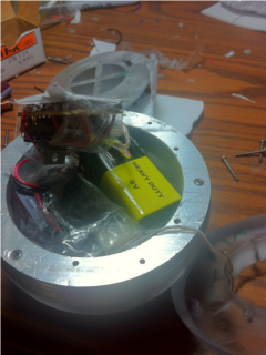
The 'top' side of the sphere contains the battery, high voltage generator (to the left of battery), and the breadboard with accelerometer (above battery). A wire is coming out of the sphere to the right, this attaches to the next aluminum disk to output the high voltage shock.
The third-to-last disk is placed on, and the breadboard remains outside of the sphere! It will have to fit in the hole in that plastic disk for the next layer to fit. There is a layer of paper on the top of the breadboard, so the soldered components do not touch the aluminum disk above them. This disk can be seen in the top left corner.
It took a while to position the relays, battery, and HV generator so that there was enough space for the accelerometer breadboard. Yet the first time I was able to put it together, the switch got locked into the off position by the pressure of the components inside, so the sphere would not work. After that I took it apart and ensured the switch would not be affected. This time the switch worked but the circuit did not, and I found that a number of wires had broken loose of the soldered connections, so these were reinforced. Finally hoping to get it working I put it together and did a voltmeter test on the aluminum disks, which showed they were all shorted together. The bolts connecting the disks were to blame, and taping them as can be seen in the images above did not help. I ended up taping a small piece of paper over each bolt that could touch an aluminum disk, which involved yet another taking-apart of the sphere. Finally, the sphere was put together and the disks were insulated properly, and I did not even bother to check whether the circuit worked until next morning.
Amazingly everything functioned properly, and throwing the sphere resulted in a noticeable shock. The benefit of having all the components packed so tightly inside is that there is no rattling, and also little chance for wires to 'wiggle' loose because there is no wiggle room lol. Also, this shows that 4 inches is about the smallest sphere size that could fit the necessary electronics, which means there is no wasted space and the planned dimensions were justified. The 4-inch diameter is definitely easier to handle than the 6-inch Original and Evil Twin spheres, which cannot be held with one hand. The entire sphere assembly has survived the lathe, which means it is well fit for use in practical throwing situations. Considering the forces normally applied to a sphere are compressional, this project should have no trouble leading a long life in terms of structural stability. The shock circuit was designed to give a noticeable but not painful shock, which makes this much more of a crowd pleaser than the Original (only slightly noticeable) and Evil Twin (excessively long shock). The sphere design also just looks professional and thought-out, much more so than a falling apart styrofoam ball. The design is symmetric, and the circuit works robustly. Overall I am happy with this project, partly due to the sentimental value of recreating a past project in a much better way, but mostly because it shows how much I have learned since then about design and construction. And that of course is the whole point of these projects.