Back in 2012 I had attempted, rather unsuccessfully, to build an electric scooter. The concept hasn't really left my mind since then; somethimes when walking around campus I would start thinking about how much faster I could be traveling with an electric scooter, as silly as that sounds. Maybe part of this was from the disappointment over the original project, but I think another part was from wanting to test out the relatively modern technologies of lithium-ion polymer batteries and brushless motors to see how they would fare in a portable vehicle application. I had read many accounts of brushless motor vehicles having very high torque, but since the motors are relatively small (compared to, for instance, 120VAC induction motors of similar power rating) I had trouble accepting such claims, and was hoping to get direct evidence with this project.
In the conclusion of the 2012 project I mentioned certain things I should have done differently: put more planning into the electrical system and high current wires, use a higher voltage rather than higher current, and plan out the gearing ratio properly. Additionally I was not very satisfied with the acceleration of that scooter, or its bulky appearance or heavy weight, or difficulty riding without electricity. Overcoming such limitations formed the overarching goal in this project - to make a compact and sleek yet definitely overpowered scooter.
I began the design with power considerations, since the physics of scooter riding is not affected much by what components are used, but it will provide hints as to what components are most appropriate. For this I put together a scientifically and mathematically questionable spreadsheet that would calculate the power lost to air drag and mechanical friction at different scooter speeds. When given motor and wheel and battery parameters, the spreadsheet also shows the torque, motor estimated power, acceleration, and ride time. As a note, I haven't confirmed the motor power or efficiency calculations, but the results should give a ballpark figure. I wanted the scooter to be fast (25 mph max speed), but also to have good acceleration (0.5 g from standstill). The gearing ratio and motor type must be selected to satisfy these criteria.
Motors can be idealized as operating in a linear fashion (brushless motors are the electrically commutated equivalent of brushed motors, so it might be more intuitive to visualize the following with a brushed motor model - the findings apply in both cases). When the motor is completely stalled, it rotates at zero angular speed and outputs its maximum torque t_max. Measuring the electrical terminals of the motor, we find zero volts across the motor (ignoring winding resistance), and maximum current draw i_max (as high as the power supply is capable of). When the motor is completely unloaded, it will rotate at its maximum angular speed s_max and output zero torque. Measuring the electrical terminals of the motor, we find the voltage across the motor is the power supply's maximum voltage v_max and zero current draw. In between those extremes, the motor's operation is defined by a line between those points. The motor's power output, which is either t*s or i*v, is maximized halfway between those points (this can be proven mathematically), and drops to zero at either point.
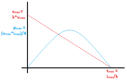
A plot showing the motor operation line (red) and motor power output line (blue) as explained above.
Mechanical gearing between the motor and the wheel can couple this power curve to the friction and drag power required to keep the vehicle moving, with any excess going towards possible acceleration. The highest vehicle speed (implying highest drag and friction power) is achieved by gearing such that the motor's rotational speed at the maximum power point matches the highest wheel speed. However gearing for highest speed means the acceleration up to that speed may be quite slow - since I intend to only use one gear ratio in the scooter for simplicity it will be desirable to gear for increased acceleration at low and zero speed, with a slight sacrifice in top speed (this also has efficiency (thus range) benefits, but a detailed calculation is design-specific and beyond the scope of this article). The effect of different gearing ratios can be intuitively explored by experimenting with a geared bicycle, where the rider acts as a 'motor' (humans will have similar power and efficiency considerations - in racing bicyclists prefer to travel at constant power and/or constant candence).
The maximum current is less intuitive to use for calculations (and manufacturers tend to exaggerate these values), so we first focus on voltage. Brushless motors have a parameter k usually written as kv, given in RPM per volt (this should appear in the motor specs). This paramater gives the motor's unloaded speed s as a function of applied voltage v. The maximum voltage, v_max is determined by the battery choice, and then s_max=k*v_max. This maximum voltage should be within the motor specs to make sure a high voltage doesn't burn through the insulation of the windings. Since power conservation requires that v*i=s*t, we find t_max=i_max/k. So ultimately k is an intrinsic 'electrical gearing' of the motor: a higher value means a faster but lower torque motor, and a lower value means a slower but higher torque motor - everything else being equal. Since I am looking for traction, a high torque is desired, so a k value of 100-300 will be used. For comparison, brushless motors for a quadcopter are in the 2000-3000 range, an order of magnitude higher.
From the original scooter project (which ran on a 12V lead acid battery), I learned the hard way that high current at low voltage is a poor way to make a compact vehicle. Typical projects of this sort use 24V battery packs. But this scooter needs more power so I set my mind on 48V. Unlike the heavy lead acid battery of the old scooter, this one would use the approximately 3x higher energy density (weight- and volume-wise) LiPo batteries that are readily available on hobbyking among others.
Some nomenclature is useful for picking the right LiPo battery: a single 'battery' will usually consist of multiple inner 'cells'. Each cell carries out a chemical reaction which sets a voltage per cell of approximately 3.7V. The batteries (or battery packs) might be labeled as 3S1P which means there are 3 cells in series, and only 1 parallel path. 3S2P means two 3S1P units have been placed in parallel. As with capacitors, placing cells in series will increase maximum voltage, while placing them in parallel will increase maximum current. Each cell has a nominal voltage of 3.7V, so a 3S1P battery is also an 11.1V (=3.7*3) battery. Maximum safe voltage limits for a cell are 3.0V to 4.2V (recall the recent exploding electronics on the news - a result of improperly used LiPo cells!). To extend battery life, it is recommended to not go below 3.4V or above 4.1V, but this of course reduces usable capacity. In case of a LiPo battery fire, try your best to move the battery outside (or open all windows for ventilation) and onto a non-flammable surface (concrete, sand, rocks) and wait for the fire to die out. Cover with sand or dry soil if practical to reduce fume dispersion. Water and most fire extinguishers will not stop the fire since the reaction with exposed lithium is self-starting on exposure to air or water. Fire extinguishers and water can be handy in case objects next to the battery catch fire.
Two more figures of interest describing batteries are the capacity (given in amp*hours (Ah) or milliamp*hours (mAh)), for instance 5000mAh (I guess 5000mAh looks more impressive than 5Ah so sellers will use the former), and the C (current multiplier) rating, for instance 50C. Logically, the capacity represents how many hours the battery will operate when it has to supply a certain current - a 5000mAh battery can operate for about an hour while supplying a current of 5A. Like cell voltage, the capacity is not really constant but depends on the discharge current - if the above battery were supplying 10A instead of 5A, it would operate for less than the half-hour that would be expected ideally (higher current reduces effective capacity, excess energy goes into heating the battery). The C rating represents how much current the battery can safely supply continuously - this is a unitless number that acts as a multiplier on the battery's capacity in Ah. A battery with a 5000mAh (=5Ah) capacity rated at 20C can be discharged at up to 5*20=100 Amps. Drawing more than 100A from this battery is dangerous for the battery. Keep in mind that this multiplier is only for discharging the battery; charging should be limited to 10C, and I usually don't charge above 1C since I'm not in a hurry (just like effective capacity is lower for high current discharging, it becomes lower for high current charging). It is not always preferred to maximize C, since lower C batteries will tend to have a higher energy density. (Ok I think we've got five tradeoffs now - is that enough?) Since most people buying batteries will have a voltmeter but very few will have a discharge current and capacity meter, the last two battery parameters tend to be exaggerated by online retailers, and on the especially cheap batteries may be outright lies (a friend had a pack on which the outer sticker peeled off to reveal the less impressive actual ratings underneath), so use your judgment - a high current and high capacity battery will be big, heavy, and expensive, so if it's not one (or all) of those compared to similar models then some numbers may have been fiddled with.
Perhaps instead of buying batteries from hobbyking it is easiest to buy a complete battery pack, that looks like a plastic box, of the sort used on e-bikes. Those packs come with a battery management system (BMS) which ensures that all the LiPo cells that are in series stay at an approximately same voltage (the BMS also provides overcurrent and overvoltage protection capabilities). With 12 cells in series, it is likely that over many cycles of riding the scooter and recharging the batteries, one of the cells may end up at a lower or higher voltage than others. This would lead to overcharging of cells and explosions, so should be avoided. For this reason, 'bare' LiPo batteries come with not only two thick wires used for charging/discharging, but with n+1 (where n is number of cells in series) thin wires which are used to balance the cell voltages. Typically one wire is the negative terminal (0V), the next one is the first cell (3.7V), next one is the second cell (3.7+3.7=7.4V), and so on. One approach to keeping these batteries balanced is to buy a balancing charger, then connect it to the balance leads of the battery at every charge. However this approach requires that all of these leads (12 for my 12S setup) be exposed outside the vehicle frame (or even worse, that the frame be opened at each charge to access these leads) - this looks very messy and creates increased risk of accidentally ripping/cutting the wires on a frame edge or of making a wrong connection. Instead I install a BMS (search ebay for 'lipo bms 12s') that will be permanently connected to the batteries and installed inside the scooter frame. This way only two wires for charging are exposed outside the frame, balancing is performed automatically, and I can bypass the BMS when connecting the controller since I suspect the BMS will not play well with regenerative braking (even if it is within the current limit, the sudden switch from drawing current to supplying current may cause it to trip). Will this keep the batteries balanced as claimed? It seems to be working so far (5 charge cycles).
Back to scooter design: I already had my mind set on 48V (which translates approximately to 12S1P LiPo cells assuming a charged voltage of 4V), and I wanted to get a real world estimate of the necessary capacity to get a decent travel range. Fortunately a number of people have published their findings from similar projects, so I went with the 'Zippy Flightmax 5000mAh 3S1P 20C' battery - namely four of them which I will wire in series to achieve the desired 12S1P layout. At 20C, the maximum current is 100A, and maximum power is roughly 48V*100A=4800W, which is much more than the controller or motors will reasonably use.
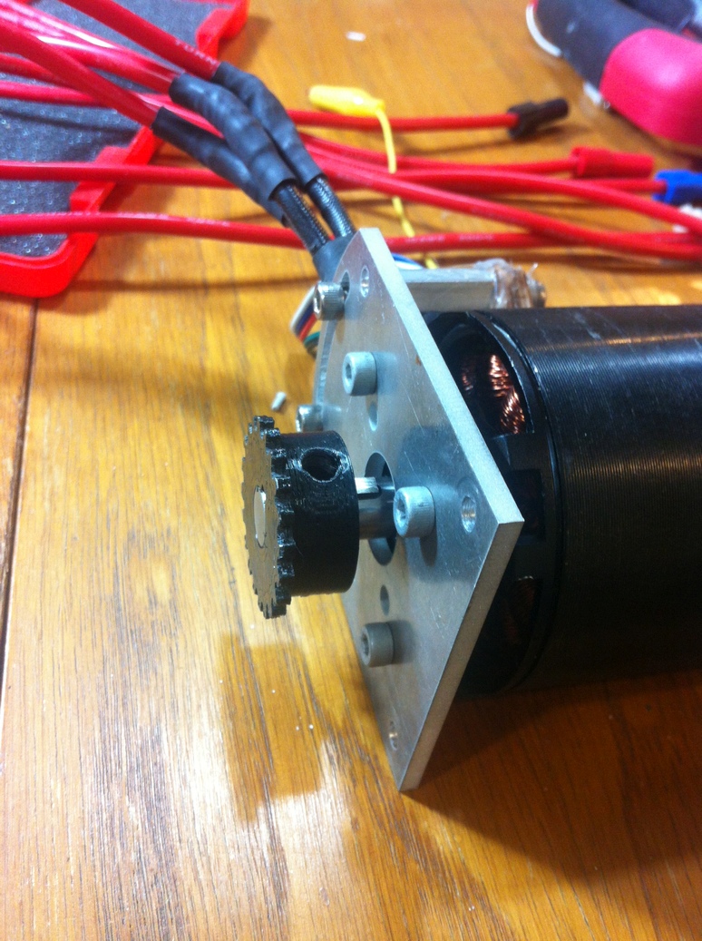
With the batteries chosen, I know the maximum voltage v_max = 48V. I had already bought the motors for a previous project so I used those - 130kv and maximum 85A current. The motors are 63mm outer diameter with a 10mm keyed shaft, which is about the size one would want for a compact vehicle application. These were from alienpowersystems.com whom I unfortunately cannot recommend as the motors came damaged (shipped without any protective wrapping), contained loose windings, and had loose set screws (good thing I checked these before depending on the motors when riding on the road!). They are also always out of stock (I must've bought the last two motors of that model they had in stock). The closest match I would suggest is the Turnigy Aerodrive SK3 6374-149kv from hobbyking as that one also has an additional stabilizing bearing on the rotor from what I can tell.
The final piece of electronics is the motor controller. This takes the 48V from the battery and creates a three-phase AC voltage that drives the motors. The most current I will get from the batteries is roughly 100A, so a 110A 48V controller is chosen, the Kelly KBS48181E (unlike hobby sites, this site lists the actual specs and has more rugged controllers, so the specs will be lower than similarly priced hobby items). In addition to the reliability of Kelly controllers, I picked this one for its regenerative braking feature - this serves as the primary braking mechanism on the scooter (mechanical backup brakes are recommended - here the backup is dragging one foot on the ground).
This project uses a sensored brushless motor controller - meaning there are three hall effect sensors (either outside or inside the motor) that sense the rotor's position. A brushless motor can also be run without sensors, but sensorless operation is ill suited to starting or braking with a high load (because it only works once the motor is spinning) - this is why on most electric skateboards the rider will need to give an initial 'push' before turning on the motor. If sensors are used, the motor controller can operate the motor effectively from standstill, and can achieve maximum torque as desired here. Since alien power systems were out of stock on their sensored motors, I bought a sensorless motor and added external sensors. These sensors must be spaced 17.143 degrees apart (more details) and should be of the latching/switch (not analog) type. I used the Honeywell SS460P which has been working great. My freehand attempt at 3D printing a case and soldering the sensors worked but looked messy, so I used the purpose-built board from e0designs.com (which comes with hall effect sensors). Since both motors here are linked together, only one sensor board is necessary.
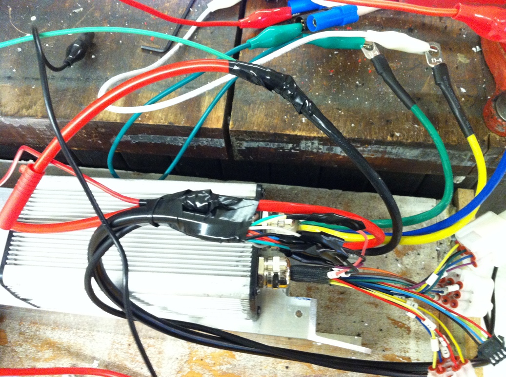
For this scooter I wanted to have both motors' power but using a single controller. The original plan was to design a custom controller, which would have worked except I wasted a few hundred dollars (and hours) on boards that I was unable to solder (with either reflow or hot air or soldering iron...). At that point I decided buying a controller would be the cheaper and easier option. But most controllers are only designed for a single motor, so I use a trick here to get it to run two motors simultaneously. The trick involves rigidly linking the motors so they are both mechanically and electrically in phase, and thus they appear as a single unit to the controller (at first I wasn't sure whether this would work in practice, but the functioning scooter is evidence that it does). To use this arrangement, both motors have to be of the same make and spin at the same speed and torque, and see the same voltage and current. In this scooter both motors are mechanically linked to each other through the back wheel sprocket with a backup shaft coupling, and electrically linked by soldering the connections in parallel (for each phase a triple joint: motor controller lead, motor 1 lead, and motor 2 lead). Please avoid using this configuration unless you are familiar enough with brushless motors to see the limitations and potential pitfalls of this approach (for instance, if the motors get out of phase they can become very effective brakes, throwing the rider off the vehicle). The mechanics behind the alignment process to get the two motors in phase are explained below.
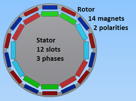
Arrangement of stator and rotor elements in a 12S14P brushless DC motor (this is the most common configuration - 12 stator slots and 14 magnetic poles). The unequal numbers lead to a magnetic equivalent of a harmonic drive, greatly increasing the motor's torque (the exact increase depends on what the comparison is made with). The stator phase colors should not be taken too literally here - refer to common winding schemes for more details.
For two 14-magnet motors (that have 12 stator slots) whose connectors are soldered in parallel, they will be electrically 180 degrees out of phase with a rotor mechanical angle difference of 180/(14/2)=25.7 degrees, which is forgiving enough to work even with a fairly loose coupling (as is the case with the chain drive). When first assembling the two motors (prior to soldering the connectors), you can take advantage of three connector permutations (of six possible permutations, since three will correspond to a reversed motor rotation) to get a mechanical adjustment step of 360/(14/2)/3=17.143 degrees. If the rotor is rigidly connected to a sprocket with n teeth such that it can only be linked at multiples of 360/n degrees, the alignment can be varied by abs(360/n - 17.143) degrees by using the differential offset between the sprocket and the rotor magnets.
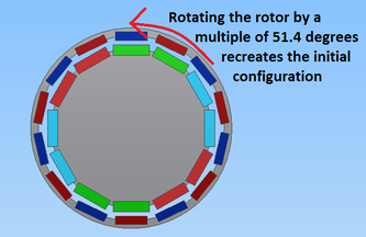
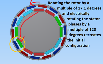
When linking two motors together so they are in phase, the coupling must be adjustable within a certain range of mechanical rotation (in degrees). Left, a straightforward rotor adjustment gives a minimum step size of 51.4 degrees. Right, taking advantage of phase permutations reduces the minimum step size to 17.1 degrees.
With all the major internal components chosen, it was time to think of how to integrate them into a frame. A major goal of the frame design was to make this project look more polished - namely hiding/protecting wires and batteries as much as possible, not being put together shoddily, not looking like adding motors was an afterthought (which was very much an issue in the original scooter project). I wanted this to be like a consumer item - the only thing I need to see, electronics-wise, is the charging port into which I plug in the charger, and there should be no regular maintenance that requires disassembling the frame. Other than that it should 'just work' - which is easier to say than to define. But a few lessons from the original scooter: the frame should allow tilting so it is possible to lean into a turn, the handlebars should be at an appropriate height, there should be a way to easily carry the device, any bolts on the bottom surface will scrape the ground and get damaged, ground clearance must be at an acceptable level (about 1.3 inches based on the Razor scooter design), the deck should be low to the ground and there should be enough clearance to the motors so it is easy to use the scooter without electric power, and there should be an easy way to adjust the chain tension if using a roller chain drive. Also the batteries need to be protected from any sharp surfaces, the motor controller and other electronics need to be protected from dirt and rain, and the controller needs to be mounted flush to a surface that acts as a heatsink.
My first instinct was to see what pieces of scrap aluminum I could find to build the frame from. Arranging the pieces I found in CAD resulted in a hacky and difficult to build frame - one that left little room for electronics (being only 2 inches across on the inside) yet was a mixture of over-engineered (using multiple 1 inch aluminum square tubes) and poorly assembled (had to use some plastic parts instead of aluminum, tens of bolts along frame edges to keep all tubes in place). This was probably the slowest stage of the project - trying to come up with a better alternative to this design, in terms of both style and ease of manufacture/assembly.
The original frame design, using scrap material and a lot of bolts. Top cover and bolts are not shown. The steering column, also not shown, will be taken from a purchased Razor scooter.
I tried to think of ways to expand the space inside the frame, perhaps by milling the aluminum tubes and then welding them... but wait, that means I'm simply on the path to a bigger aluminum tube. It turned out there was a 2 ft long 3x3 inch square tube with 1/8 inch wall thickness available on ebay for $20, so I bought that, which was probably the best decision of this project as it saved all the hassle of designing and building a multi-piece frame. The tube forms the bulk of the frame, protects electronics and batteries since they are completely enclosed, and requires minimal assembly - the components would be slid in, horizontally, into the tube, then only a few retaining bolts would keep them from coming out. I also simplified the motor holder metal plate, from a complicated 4 step machining process to a single rectangular part that could be cut on a waterjet. I inserted an accurate-enough representation of the actual steering column in CAD by taking a profile photo of the real part from far away (to minimize distortion), importing that photo into CAD and tracing over the outline, then redoing any critical dimensions with caliper measurements. The photo method was surprisingly accurate given its convenience, and definitely good enough for this model since all I need it for is checking that no interference occurs.
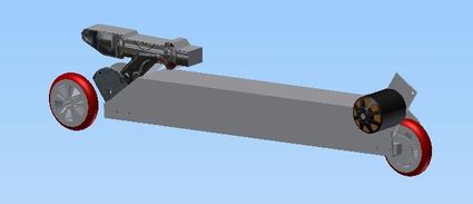
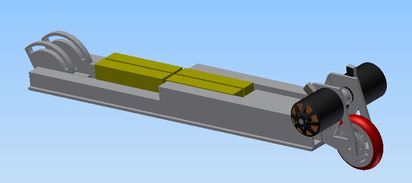
The updated and final frame design, using a single aluminum tube and some easy to machine parts. Second motor is not shown. The floating front wheel is there to help maintain a realistic ground clearance in the model.
I mentioned tilting a few times already; by tilting I mean leaning into a turn, which is crucial on a scooter. The frame design, as well as the mechanism that transfers power to the back wheel, should have adequate ground clearance so they do not prevent leaning into a turn - the store sold Razor scooters have a maximum tilt angle of about 45 degrees off vertical, so I used that as the basis. This dictated the maximum sprocket thickness and OD, the frame width and minimum ground clearance, and the motor ground clearance. I wasn't able to get 45 degrees, but approximately 40 which hasn't been a problem so far.
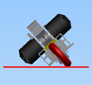
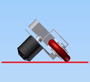
Left, maximum tilt angle of the initial frame. Right, maximum tilt angle of the final frame. Both are looking at the scooter from the back and along the direction of motion. The narrower frame of the final design gives a slight increase in the tilt, but means that the motors are the first to hit the ground.
I haven't covered the more mundane aspects of the design, so in this section all supplies for the scooter are listed for reference. Major cost components: 4 LiPo batteries - $100, motor controller - $200, 2 motors - $200, razor scooter and throttles/misc - $100. If one uses mostly scrap metal and previously purchased bolts, a reasonable minimal cost is $600 (shipping costs may drive this up).
To start, I made a prototype set of sprockets on the 3D printer to make sure I designed it correctly - turns out the resolution on the printer was not good enough to allow for a properly fitting sprocket, but this led to a redesign using a more complete sprocket profile (this more complex shape, as opposed to this simpler one, is used to allow for the chain to stretch during use - and it stretches very noticeably).
Three photos of the 3D printed sprockets. They didn't fit the chain at all due to insufficient print resolution.
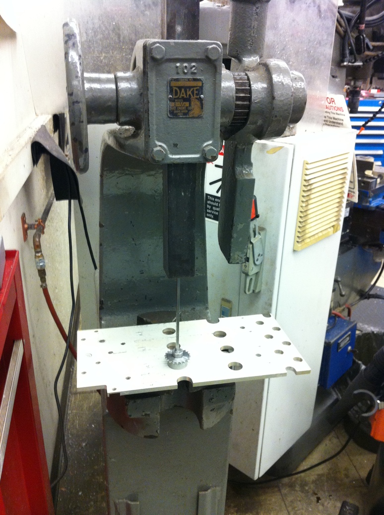
So I guess might as well try the real thing? I started by turning down the steel rod on a lathe, to a rough sprocket profile.
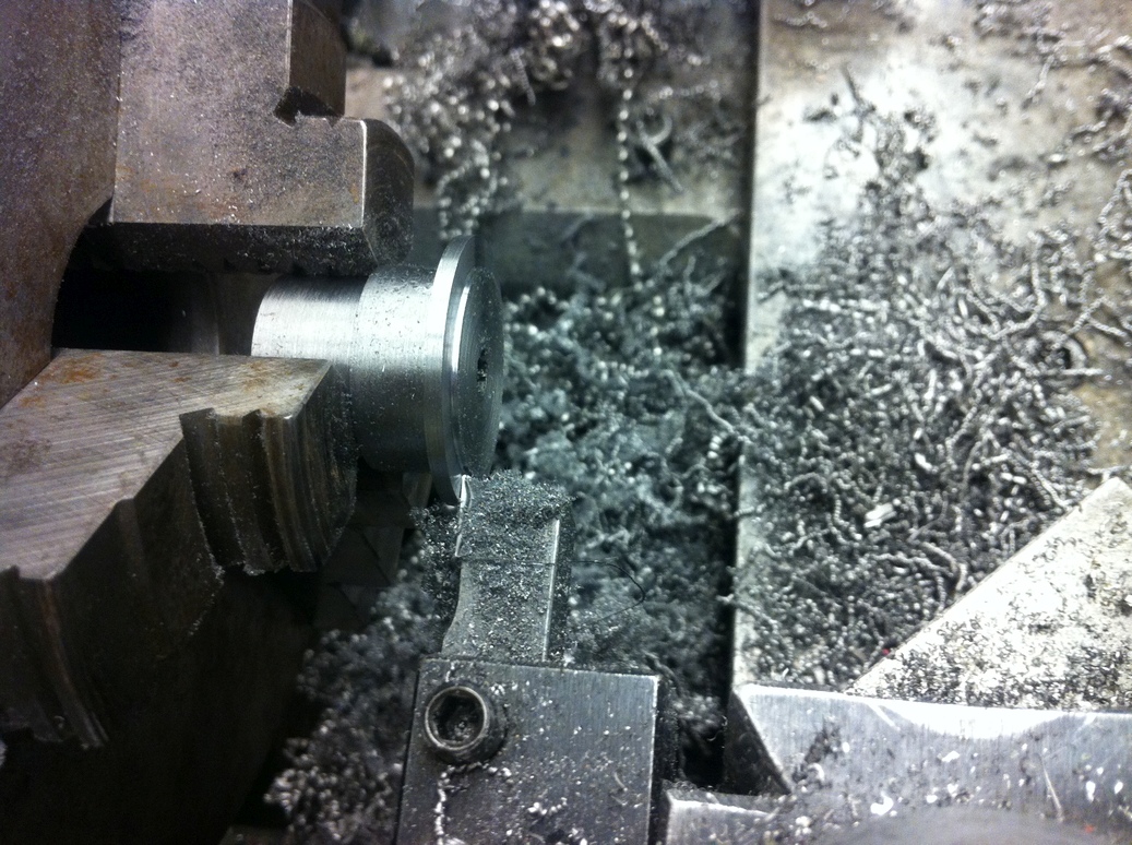
Working on the lathe.
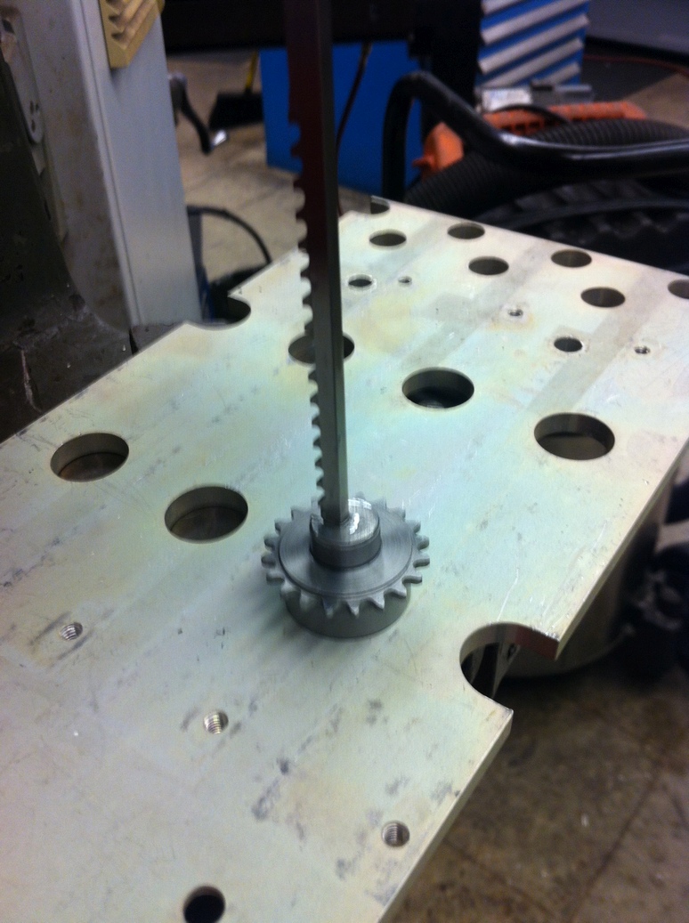
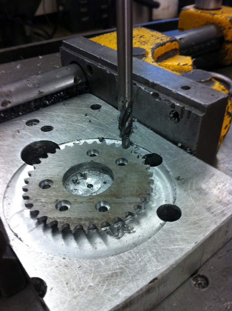
Then I milled the teeth using a 3/32 inch diameter end mill - the largest that would accurately reproduce the inside curvature (did I mention how tiny this chain is?). I broke one end mill by exceeding a depth step of 0.02 inches - this was one slow operation. For a proper chain fit, it turned out to be crucial to take multiple finishing passes - even a tiny increase in diameter would make it so the chain would not fit, and with a 3/32 end mill the deflection of the tool while cutting was enough to cause this increase. After machining, I do a quick check by wrapping the chain around the sprocket - it fits!
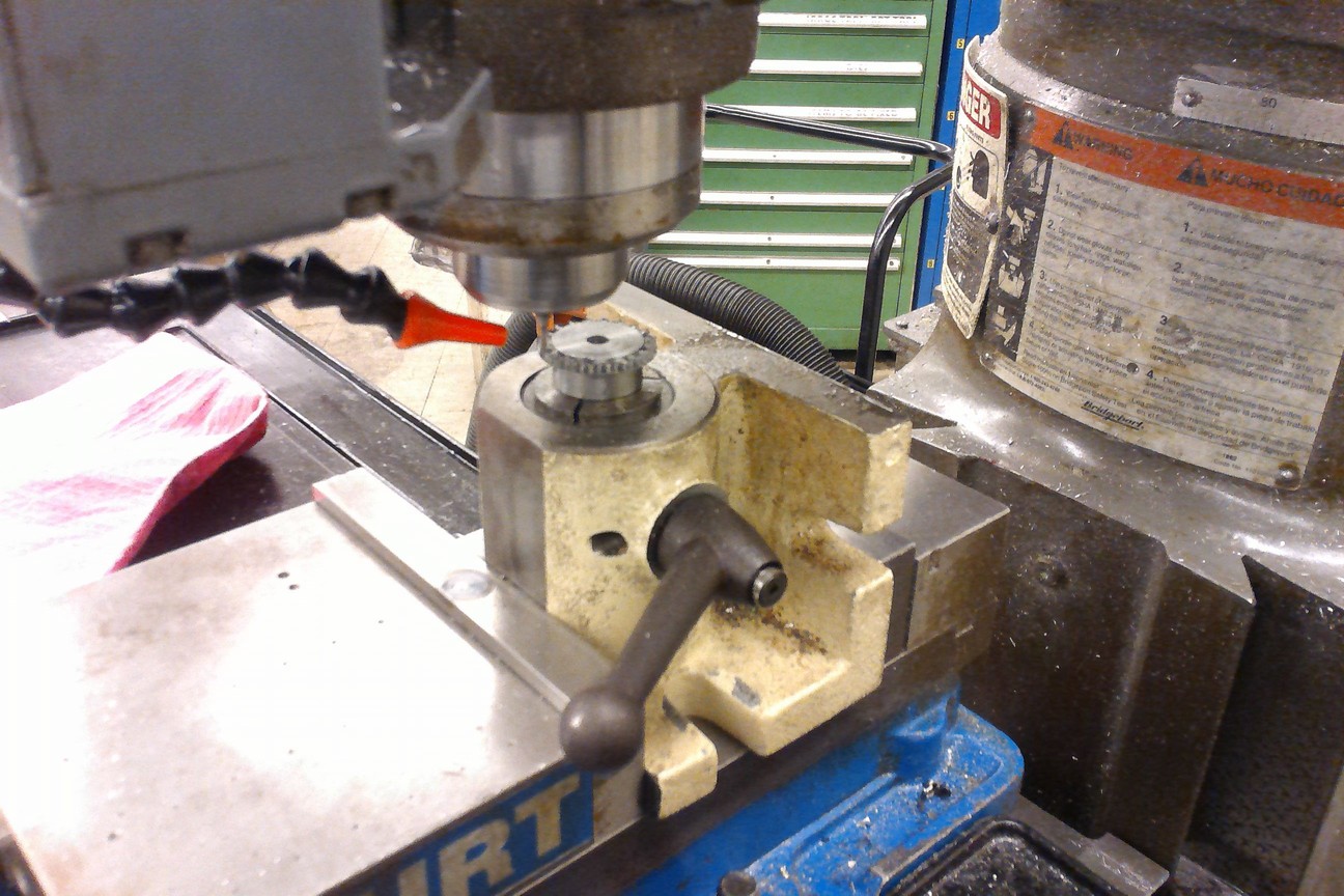
Working on the mill.
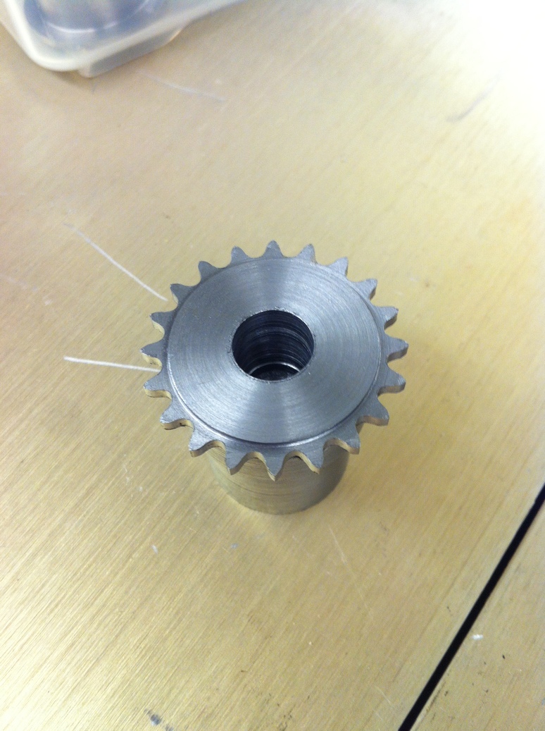
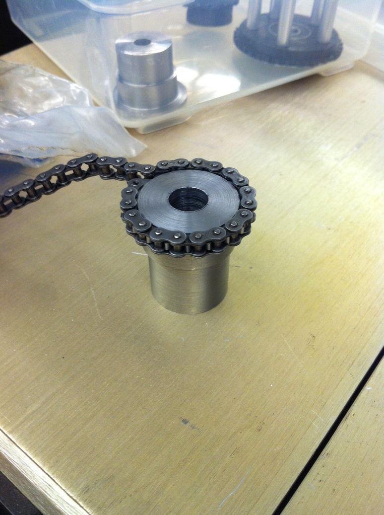
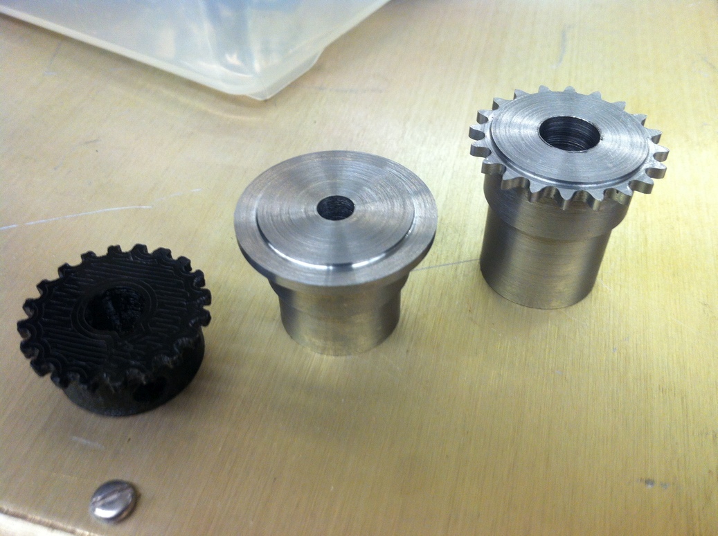
Left to right: the sprocket after teeth have been milled, testing the chain on the sprocket, and progression from 3D print to metal sprocket.
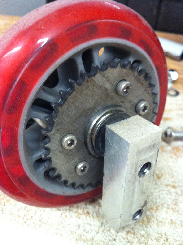
The keyway on the sprocket is machined using a 3mm broach, then two set screw holes are added (one on top of the key and one at 90 degrees to it) and fit on the motor shaft is tested.
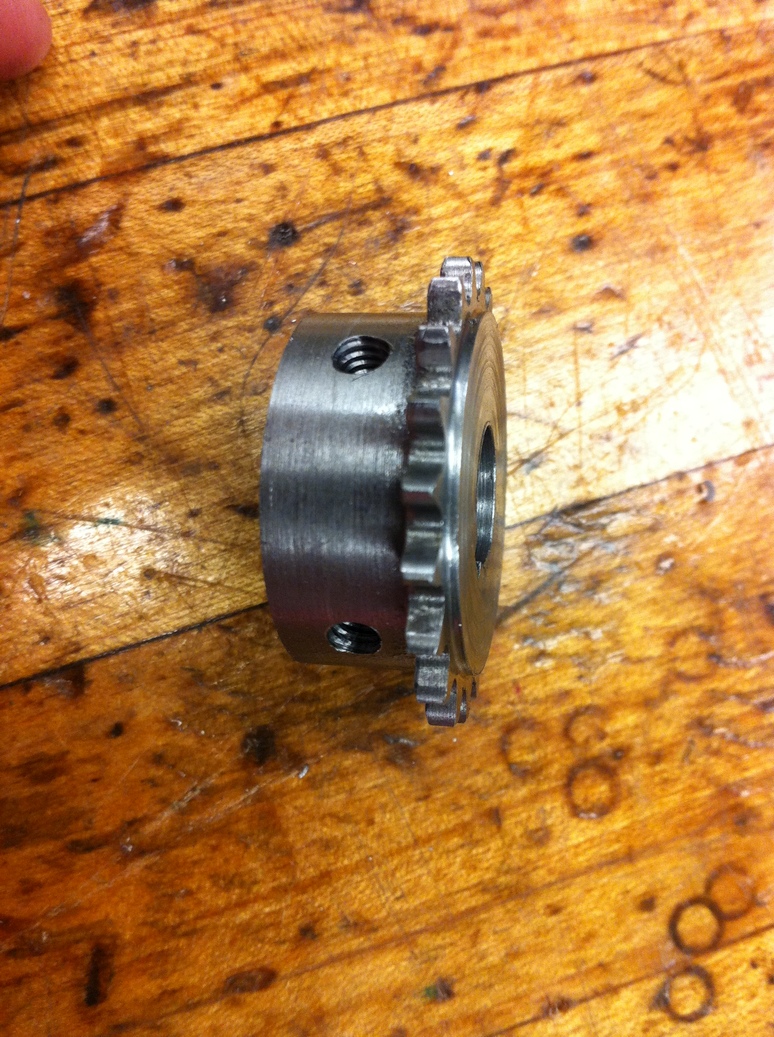
Left to right: broaching using an arbor press, close-up of broaching, and close-up of set screw holes.
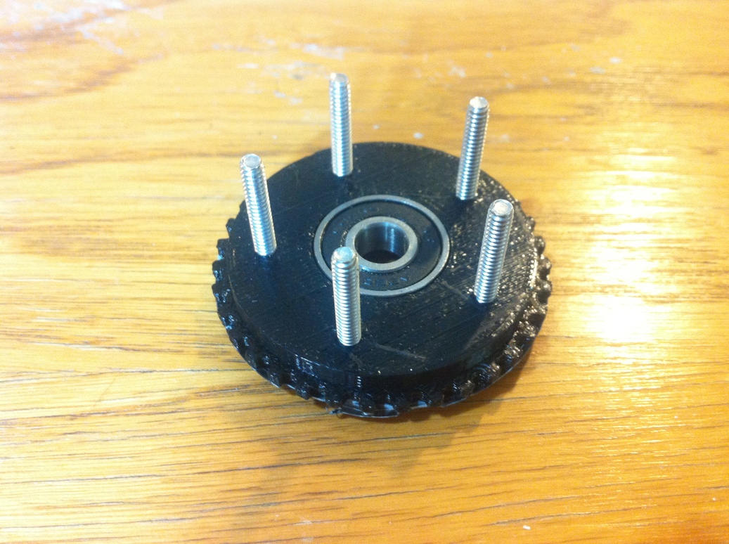
The wheel sprockets are trickier, as I do not have any way of holding them in the mill. First I milled a quick jig from a scrap aluminum sheet, that would hold the sprocket in place using its bolt holes.
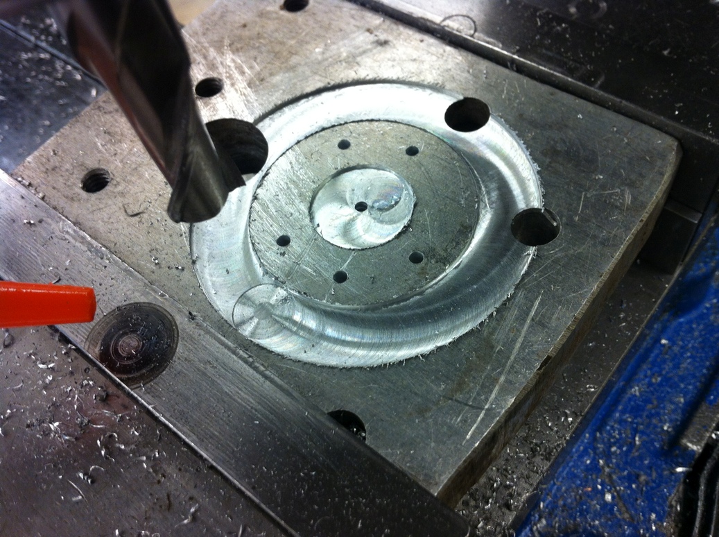
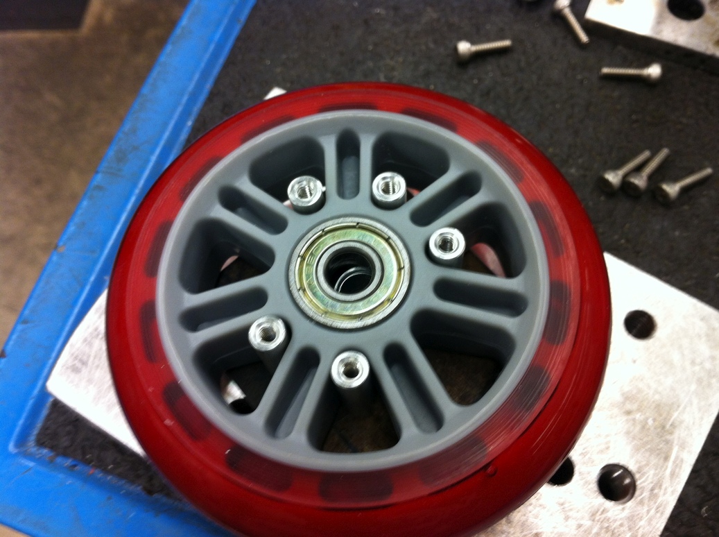
Left, the aluminum jig to hold the sprocket in the mill. Right, the five holes on the jig (and on the sprocket) are spaced to attach directly to the Razor wheel - this fit is verified with the jig prior to machining.
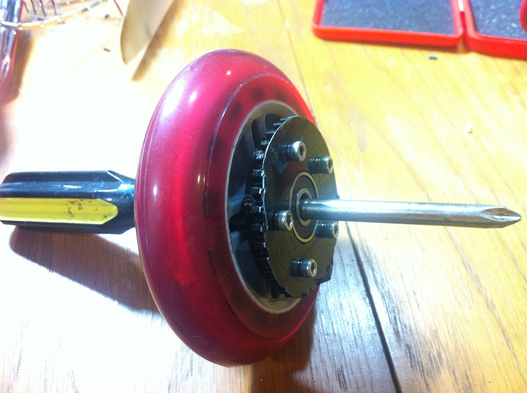
To minimize the amount of scrap generated, I begin by cutting out a square-ish shape of steel sheet (from an already cut scrap sheet) that contains the sprocket profile within it (every block of steel has a sprocket inside it...). Then bolt holes are drilled, then the stock is placed on the jig and the central hole and teeth profile are cut. Finally, the fit of the sprocket on the wheel and on the chain is confirmed. Since this sprocket is larger than the motor sprocket, even more finishing passes are necessary (four seemed to work). It turned out that the bolt heads stick too far out past the wheel, so the bolt holes are counterbored using a counterbore drill (this tool stays centered on the hole, so I am able to do the operation in the drill press rather than having to re-align everything for the mill).
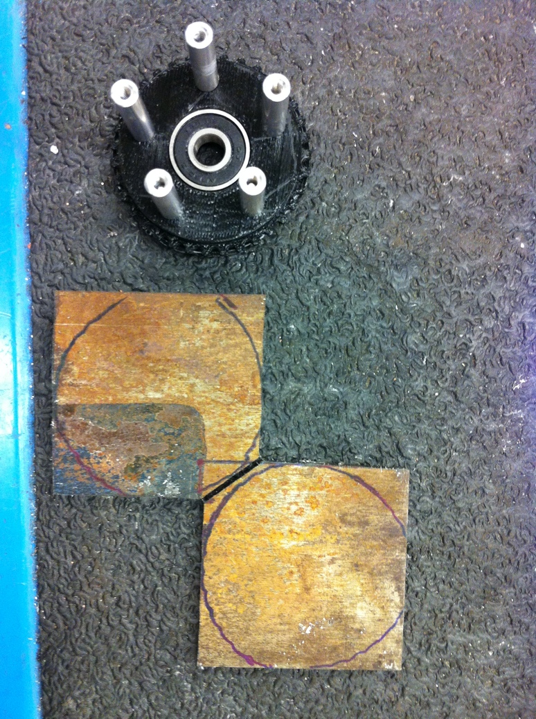
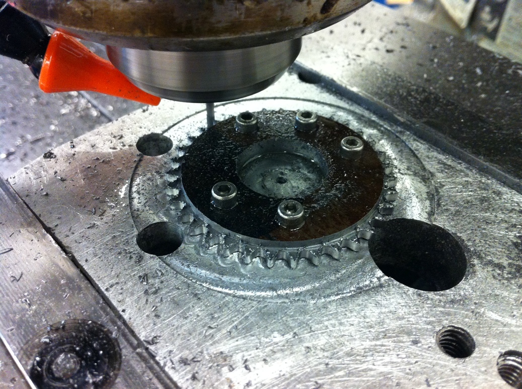
Left to right: starting from sheet stock, milling tooth profile, testing the fit of the sprocket.
Counterbore drill.
To save machining time, I used the steering/handlebars/front wheel assembly from a Razor A scooter. The first step was to take the scooter apart and measure the dimensions for interfacing with the rest of the frame.
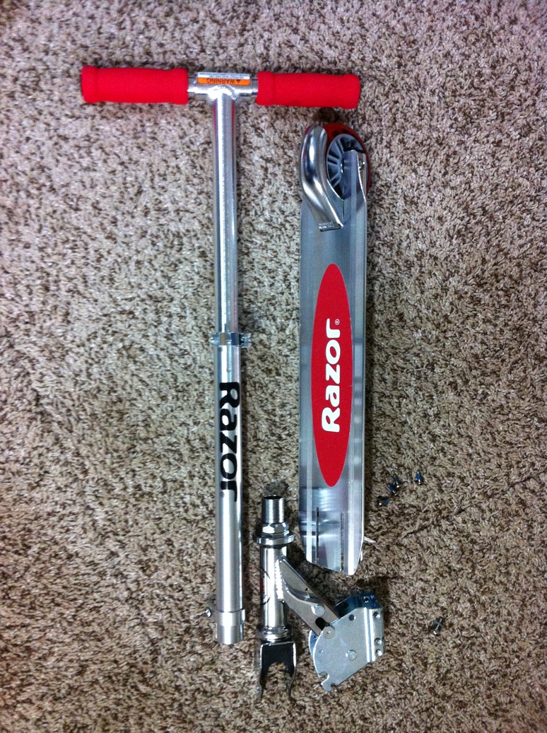
Razor scooter taken apart.
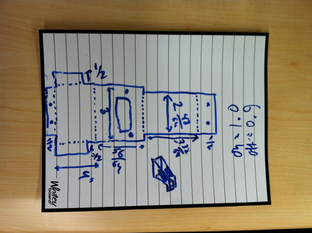
The rest of the frame components were then designed to fit that assembly and the rear wheel. I decided to go the old-fashioned way and make a paper drawing of all the machining operations, which worked out quite well. The tube is machined on the sides to make bolt holes, and then on the bottom to make a pocket for the rear wheel. Rectangular aluminum spacers are used to hold the rear and front wheels.
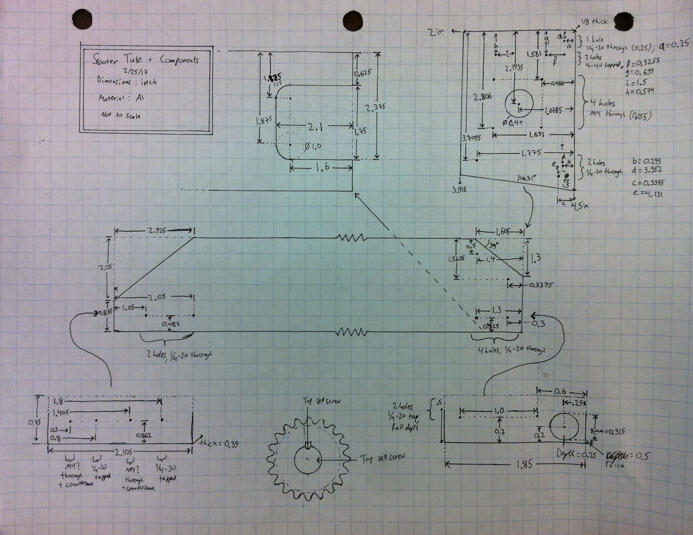
Drawing of dimensions for machining.
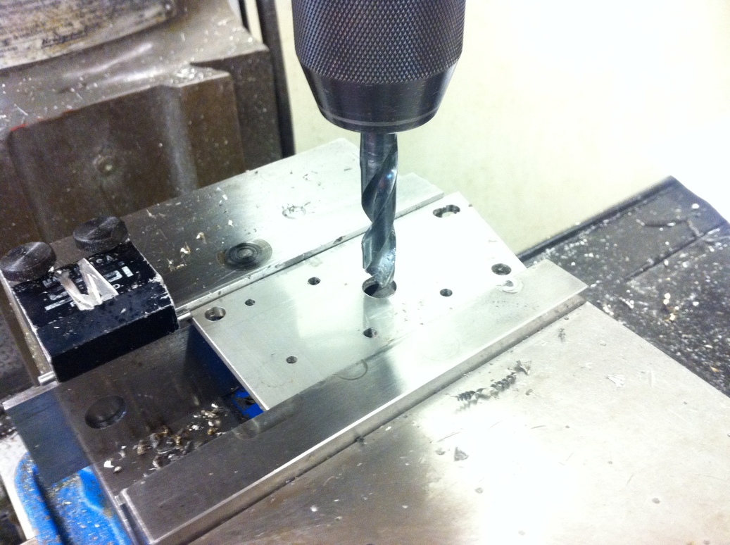
Bolt holes are drilled on the 3x3 inch aluminum tube to allow attachment of wheels and motors. Then chamfer cuts are added on the front and back ends to allow folding down of the handlebars and adjustment of motor height, respectively. To ensure the bolt holes are in a straight line perpendicular to the tube face (so they are aligned on both the left and right sides of the scooter), I used a very long center drill and drilled the holes from one side rather than flipping the tube over to drill the other side. The chamfers were done with a bandsaw, following a hand-drawn line, which worked out surprisingly well. Afterwards they were made straight using a belt sander. Then the fit of the back wheel is tested - the bolt holes were a bit off, causing difficulty in tightening, but the wheel could be secured without further adjustments.
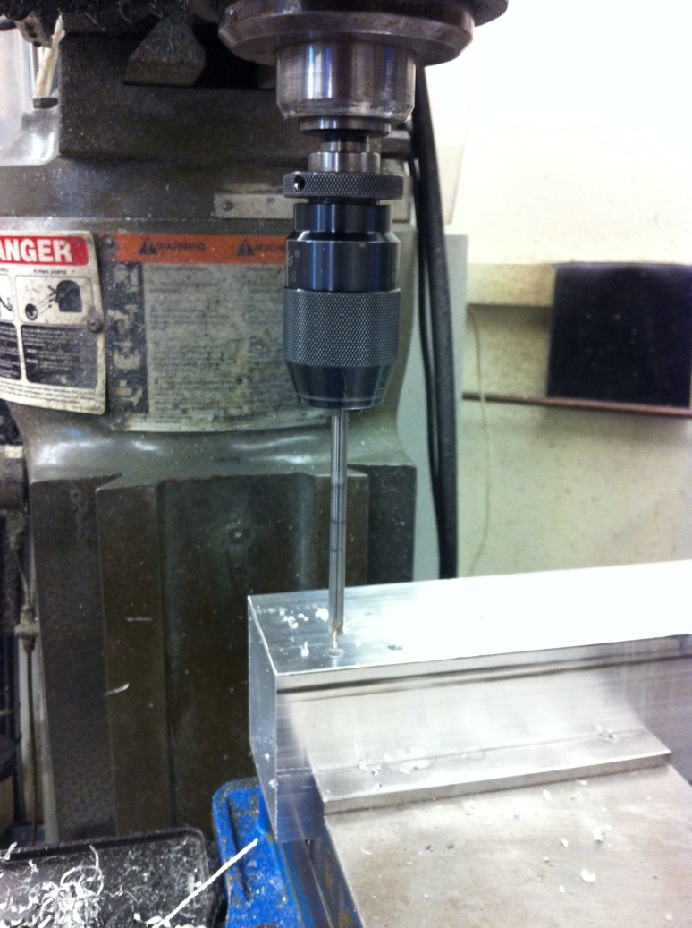
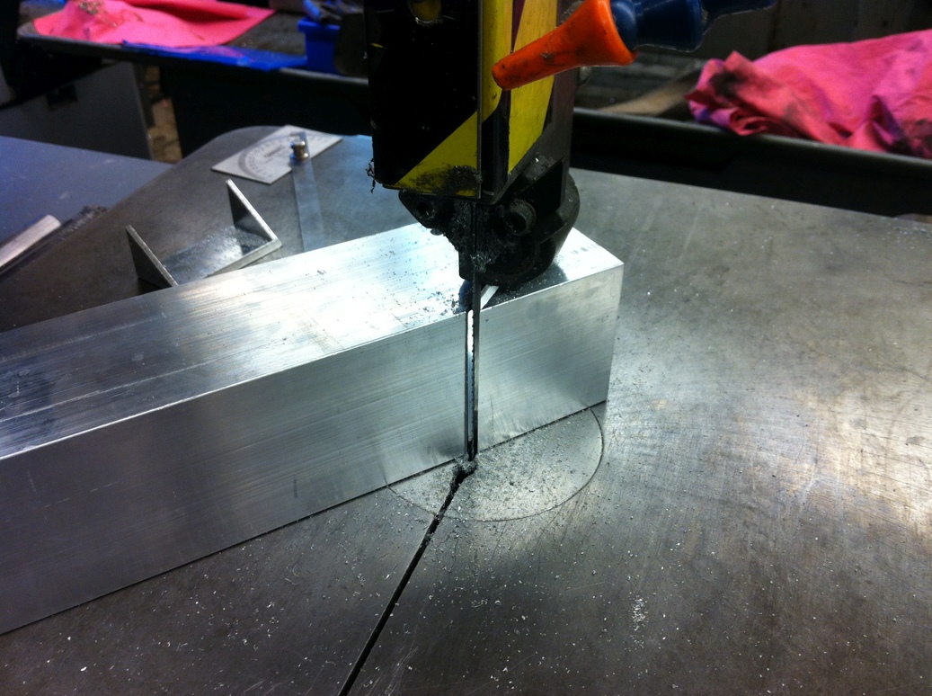
Left to right: drilling holes with a very long center drill, sawing the chamfer sections, and testing the fit of the back wheel.
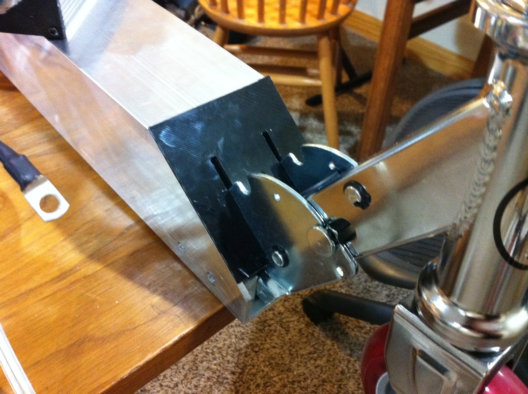
The front wheel is installed next. Aluminum blocks are milled to shape and attached to the razor scooter part. Then that assembly is inserted into the front of the tube. Handlebars can be folded down (at least for now, while the motors are not installed). With the front and back wheels in place, it was time for a manual ride test. Many bolts came loose from the vibration, but otherwise the structure held up fine. My biggest concern was the size of the aluminum supports but FEA gave a minimum safety factor of 4, and they have held up so far. The most obvious plastic deformation occurred in the bolt holes on the tube (same as for the Hoverboard, although I used bigger bolts here specifically to avoid that - the threads act as a stress concentrator), both due to a slight mismatch between hole locations on the tube and other components, and due to loading during riding.
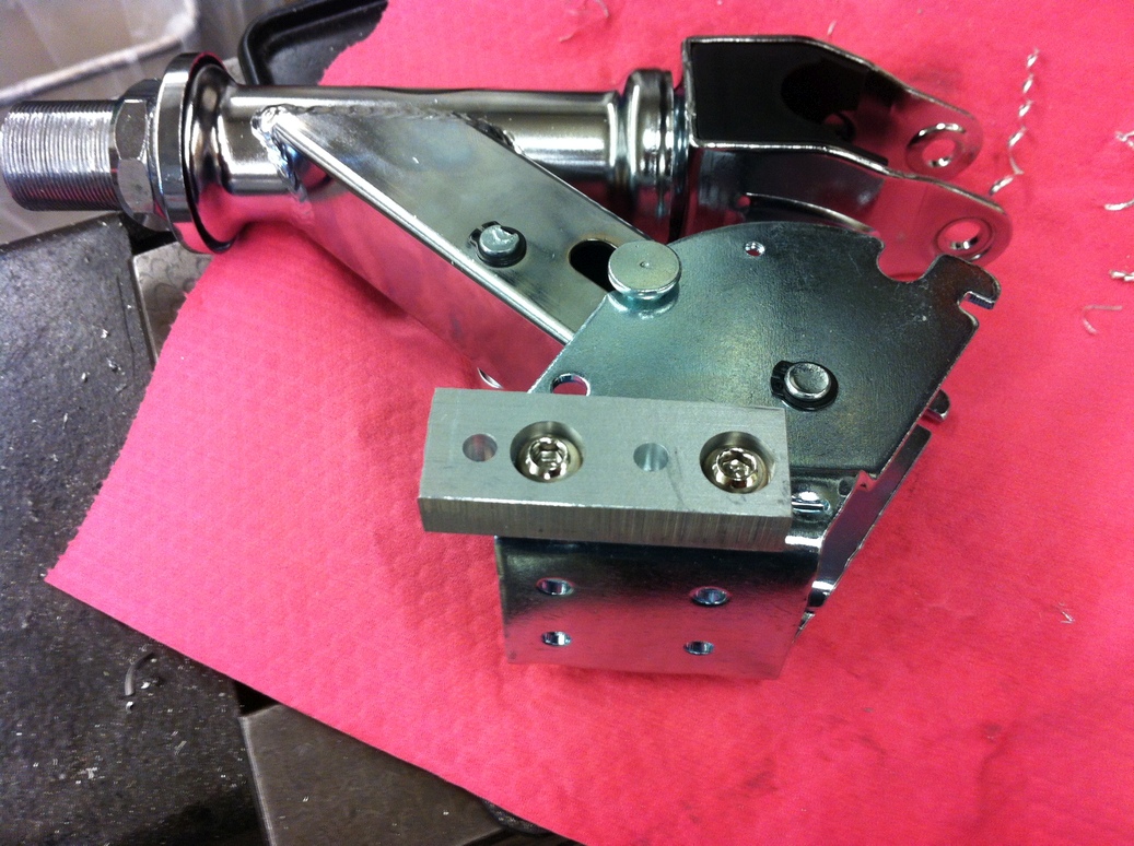
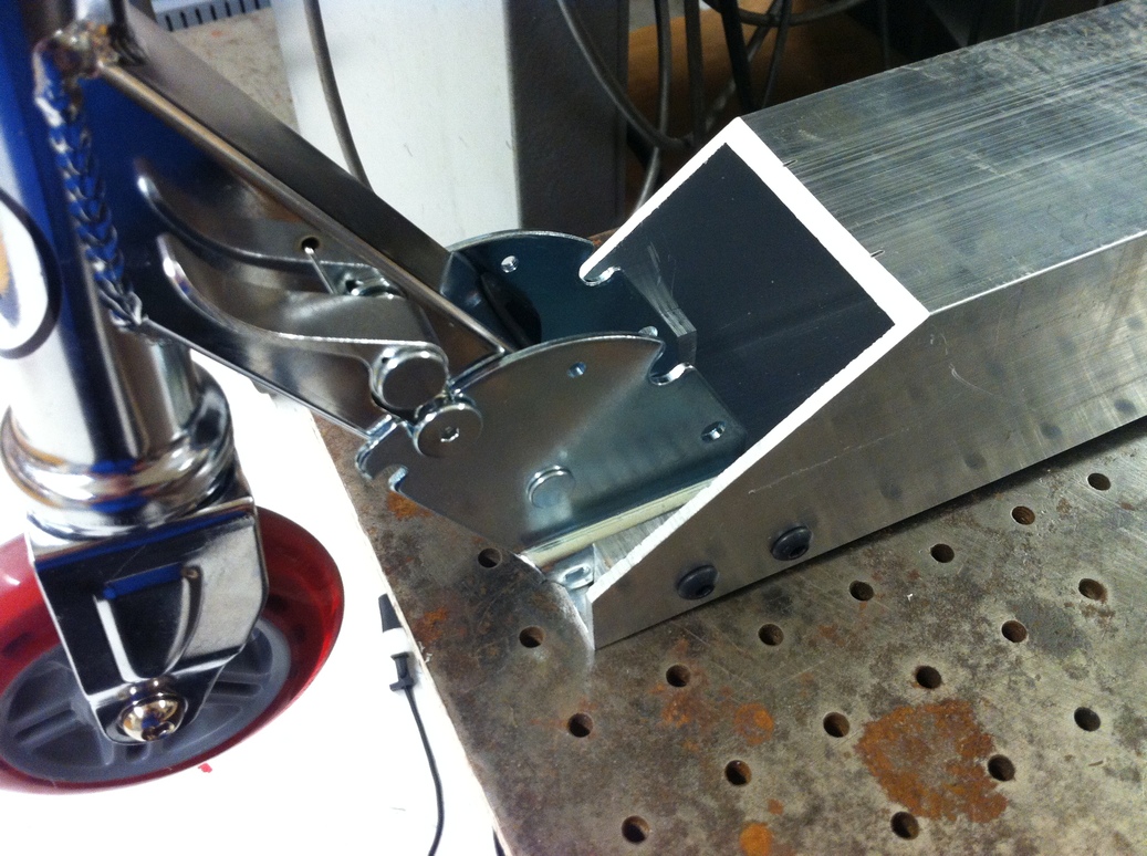
The aluminum blocks aid in attaching the razor scooter part to the 3 inch tube. The chamfer cut is designed to allow the handlebars to fold down.
A 3D printed dust cover for the front of the scooter is installed.
During the test ride it was clear that the handlebars were too low. A steel tube was machined to replace the aluminum tube that arrived with the stock razor scooter. The handlebars were raised by 5 inches - 3 to account for the 3 inch aluminum tube, and 2 for added convenience. An important point here is to match the design of the original tube - note the seemingly unnecessary rounded holes where the tube attaches to the rest of the assembly at the bottom and at the top. These reduce the likelihood of cracking by spreading any stresses over a smooth area (as opposed to sharp corners), and should be replicated in the replacement tube. I did my best with the hand tools available in the lab; it hasn't cracked yet?
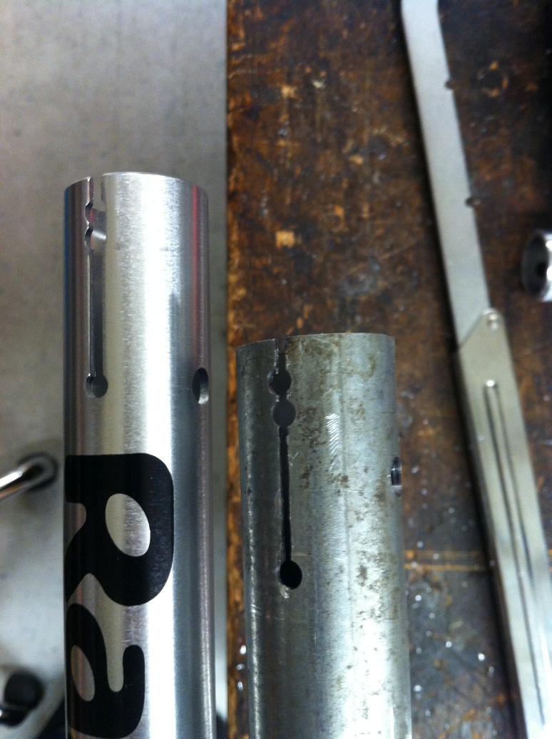
Comparison of the cut-outs on the original razor scooter steering tube and the longer steel replacement tube.
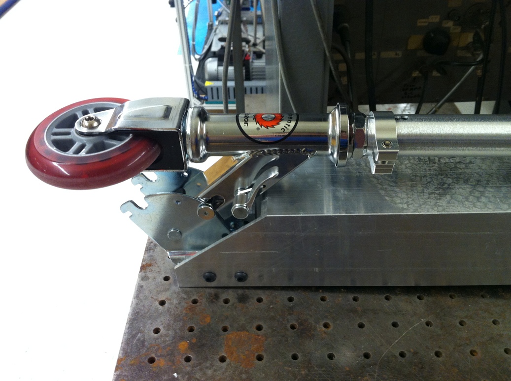
Next the motors are attached. The motor holder is a 1/8 inch thick steel sheet with holes to attach the motor to the frame. The lower hole that attaches to the frame is made in the shape of an arc, in order to allow chain tension adjustment by rotating the motor holder about one of the bolts. The Machinery's Handbook provides the following recommendations: the sprocket center-to-center distance should be more than 1.5*(sprocket diameter) and less than 30*(chain pitch). The large sprocket diameter in this case is 2 inches, and chain pitch is 0.188 inches, leading to limits of 3 inches to 5.6 inches. Furthermore, chain length should be adjustable to be up to 1.5 chain pitches longer than the nominal length (this would be done by a tensioning mechanism, in my case manually moving the motors), in order to allow for chain stretch during use. Furthermore, for an application where power will be transferred either from or to the motor (as here, during accelerating and braking), the sprocket centers should be in a vertical line to avoid chain 'droop' due to gravity. Finally, the chain should have an even number of links so that a standard coupling 'master link' can be used instead of an offset or half-link. Since one goal of this scooter is to be portable, I use the smallest recommended center-to-center distance of 3 inches, which turns out to be approximately 60 chain links. Then I find the theoretical sprocket center-to-center distance for a 61.5-link chain (representing a stretched 60-link chain), which gives a maximum center-to-center distance of 3.16 inches. The Machinery's Handbook formula for center-to-center distance given number of chain links, chain pitch, and sprocket teeth is employed for the calculations in this spreadsheet. Experimentally the above recommendations and the formula have proven to be correct, despite the tiny chain pitch (and the ability to re-tension the chain was absolutely critical, as the new chain stretches even after minutes of use).
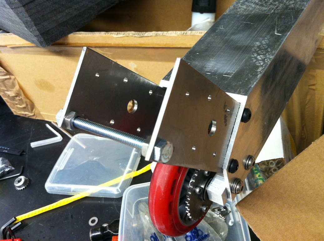
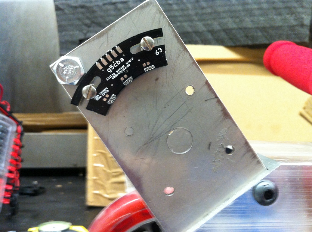
The bandsaw-cut steel sheet is drilled using a mill with DRO. Both motor holders are attached to the frame, with a 3 inch bolt between them at the far end used to prevent a 'tuning fork'-like oscillation. The placement of the hall effect sensor board is also verified.
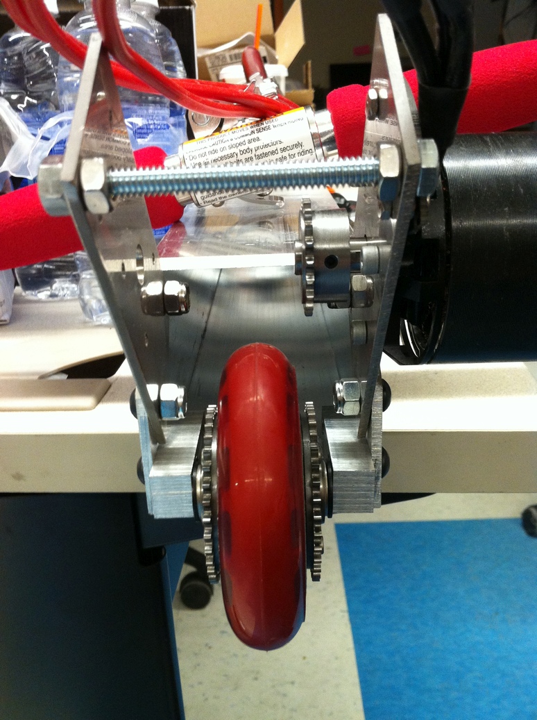
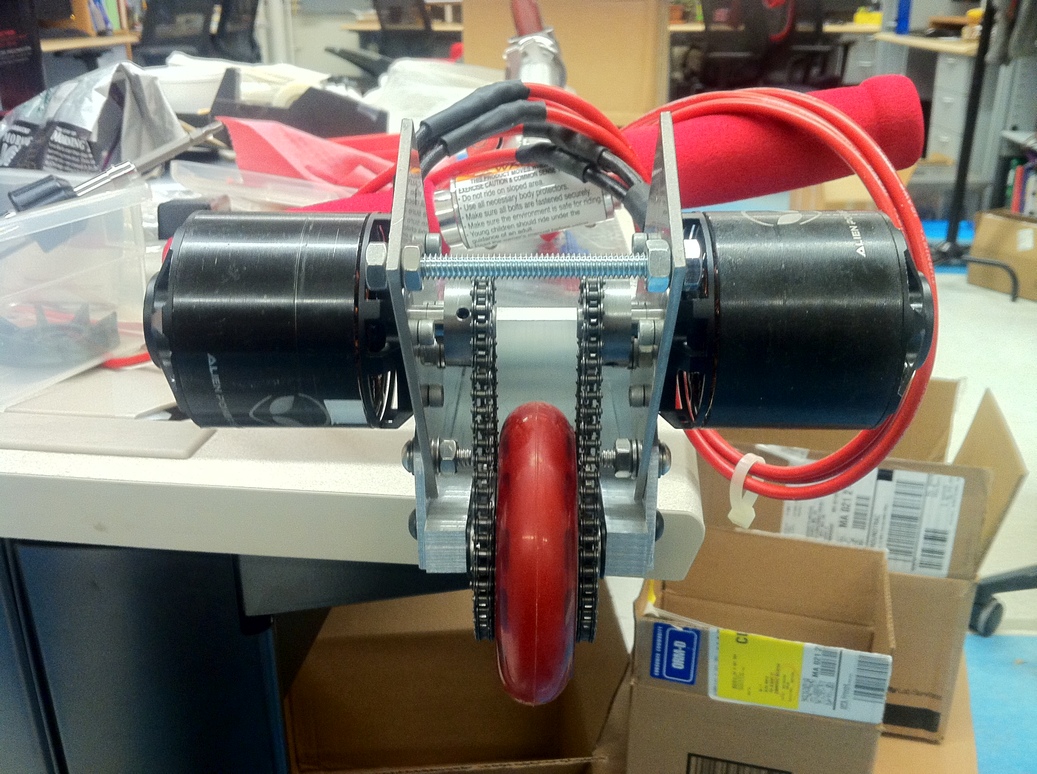
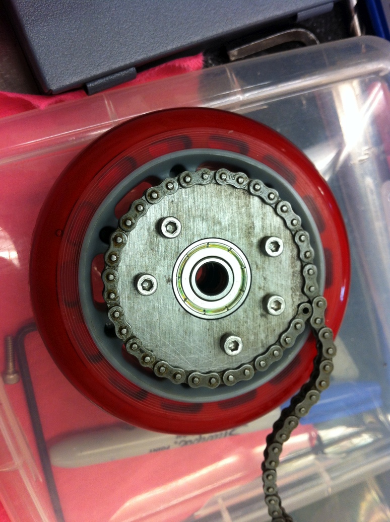
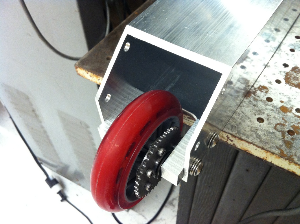
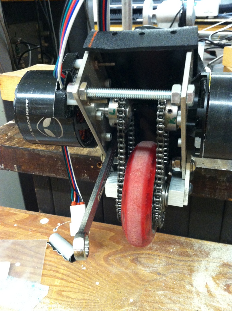
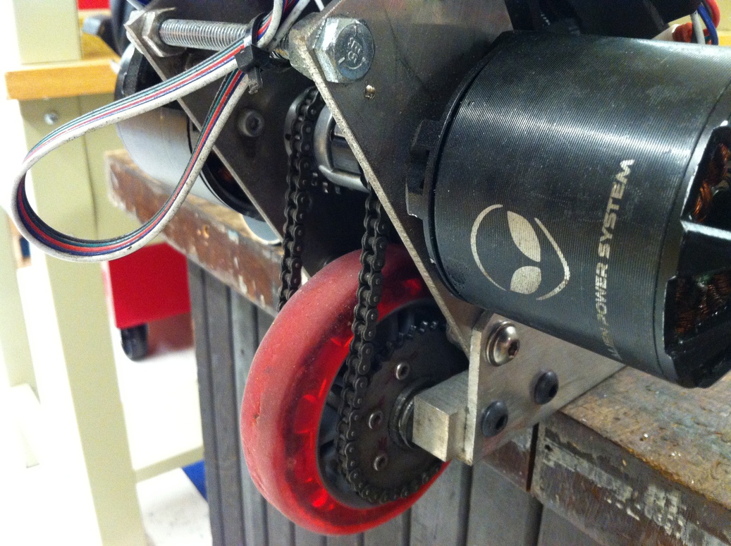
Both motors and roller chain are installed. Everything fits!
Time for a spin test! At least it sounds fast. The sprockets ended up being a bit off center which causes the repetitive 'crunching' sound in the video, but the error is small enough that it doesn't affect functionality. A spring tensioner would help in theory, but because the chain is also used for braking a simple cantilever design would be insufficient.
The scooter uses four batteries. They need to be held securely inside the aluminum tube. These LiPo batteries are extremely sensitive to being punctured, so all sharp objects must be kept away - including any sharp edges (even plastic) inside the tube and facing the batteries. To ensure all the electronics fit inside the tube, I 3D printed an enclosure that would hold the batteries in place, and provide a way to lay out the wires such that they fit within the available clearance. This was an extremely helpful step, which had the added benefit of protecting the batteries from being caught on potential sharp edges as the batteries are inserted into the tube. Unlike the messy wiring on the Hoverboard, here I took advantage of the leads coming from the batteries by twisting apart the HXT connectors into individual red and black wires, which could then be run to other batteries to create the series chain. With this approach, no soldering at all is required to wire the batteries together.
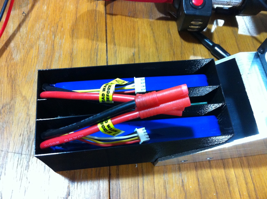
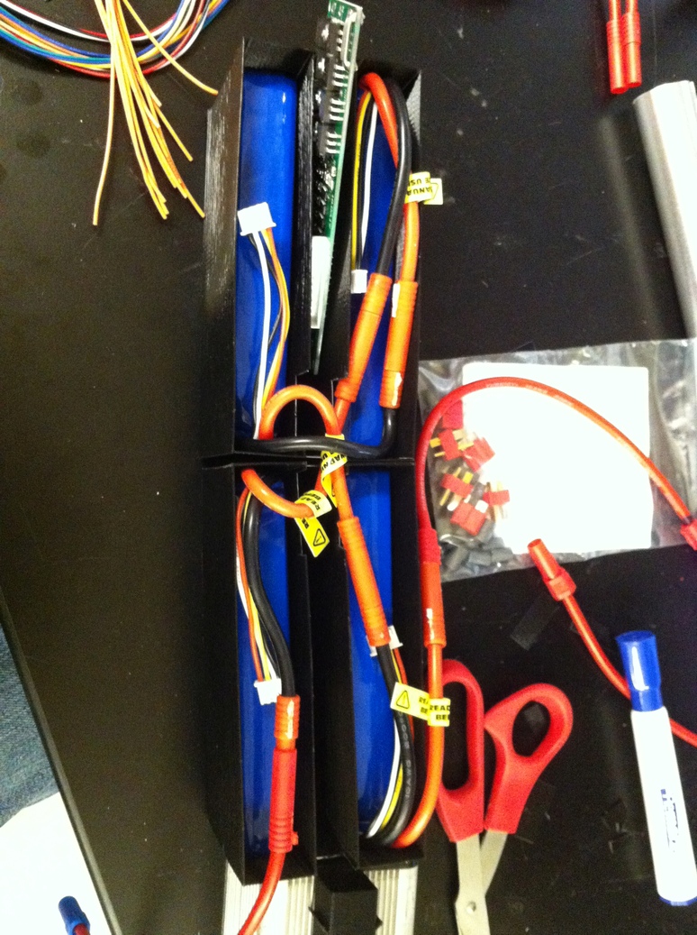
Left, the fit of the batteries in the 3D printed protective housing is confirmed; the housing also fits inside the aluminum tube. Middle, batteries are easily connected in series after separating the black and red wires of the HXT connectors. Right, the BMS is connected.
This motor controller was chosen for its regenerative braking capability. In order to activate braking, two signals are required - one pulling a 12V pin to ground to signal that braking should be used, and another 0-5V level to signal the braking torque. This can be done with an electric pedal which has a built in switch and potentiometer. Since I have a brake throttle that does not come with a switch, I need a way to activate braking by only measuring the throttle output. This is done by connecting a hastily built inverting Schmitt trigger circuit to the output (as opposed to just a comparator, this adds hysteresis to avoid high-frequency alteration between braking on/off if the throttle is held at the comparator threshold). There must be more elegant ways to do this with a diode and transistor, but for simplicity I used an op-amp circuit which draws an embarrasing 10 mA (the motor controller draws 30) to keep a stable voltage reference despite the large (12V) output voltage.
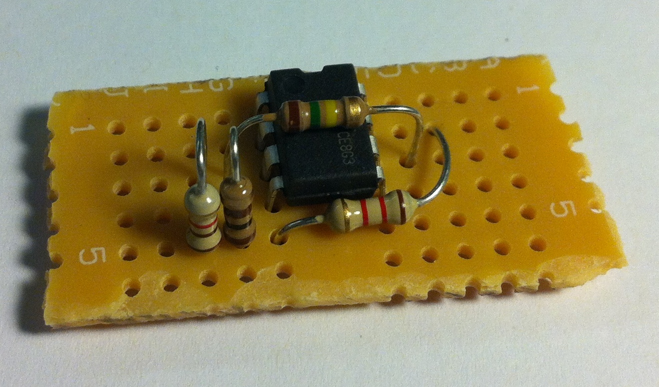
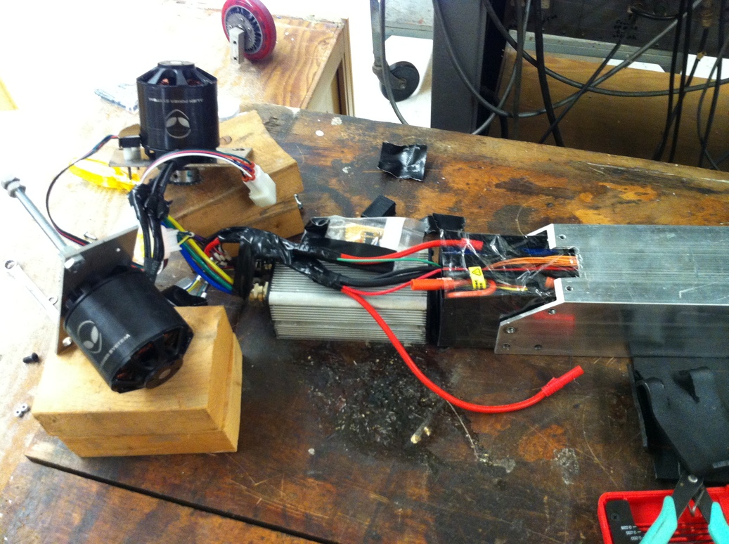
The op-amp circuit is soldered on a breadboard (it's been a while since I've done that!). Then everything is wrapped in tape and soldered to the motor controller. The non-soldered connections include battery (using HXT), motor wires and hall sensor wires (to be soldered later).
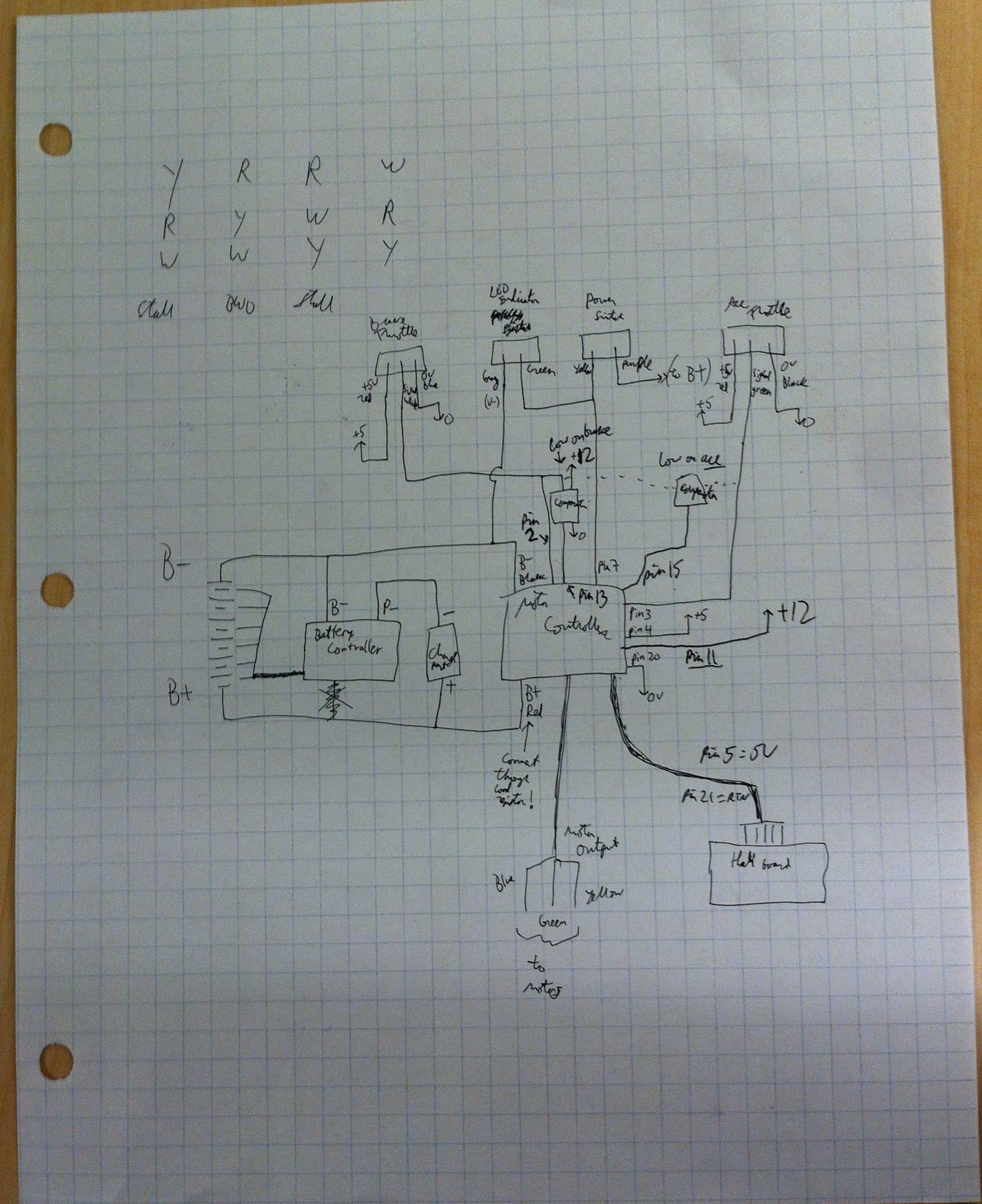
A messy drawing of the wiring inside the scooter, including motor controller pins.
The resulting assembly needs to be inserted into the aluminum tube, exposing only the charging port at the front and motor wires at the rear. To keep everything in place, and insulate the electronics from the top of the tube, the 3D printed pieces with all wiring complete are wrapped in tape. Then the electronics are pressed into the tube (it ended up being a very tight fit, taking around 40 lbf to press in). Everything fits! A spin test is carried out to make sure none of the wires have come loose.
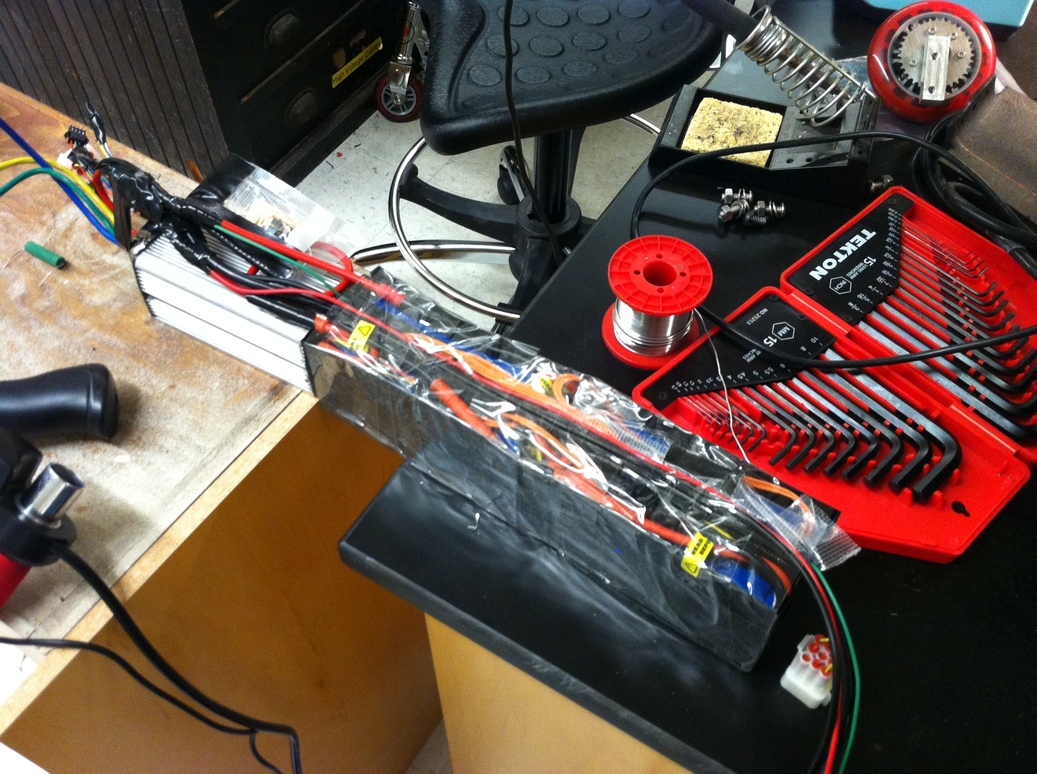
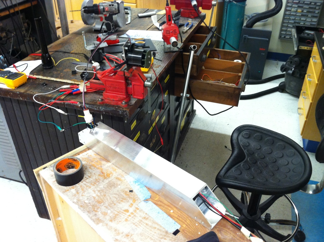
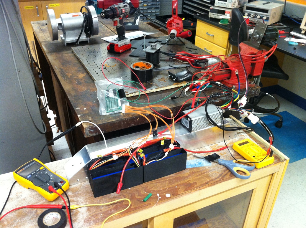
The tape-wrapped electronics block is pressed inside the aluminum tube, then hooked up to a motor for pre-assembly testing.
Some protective elements needed to be added to make the scooter more durable and robust. First I 3D printed a cover for the hall sensor board. It is designed as a snap fit, which I also hot glued for extra holding power.
The hall effect board is covered with a 3D printed part.
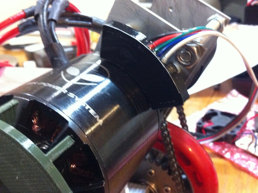
Fabricating the next part, which was largely unplanned, is probably my second best decision in this project. This is a two-part protective plastic cover, which keeps the wires largely shielded from the wheel and chain, both to avoid debris and to remove the possibility of a wire being cut by the spinning elements. Additionally the cover provides support to keep the electronics from sliding backwards into the wheel. I made the part by forming a kydex sheet with a heat gun, following the precise dimensions of the engineering drawing.
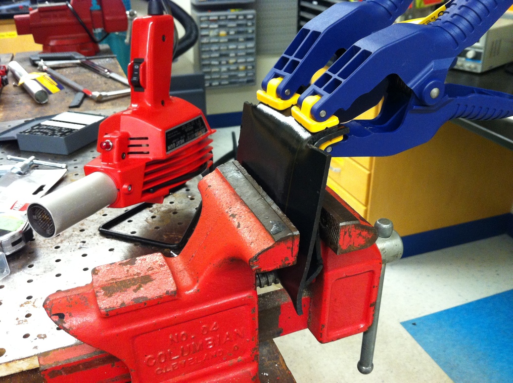

The protective cover is formed with a heat gun and clamps to ensure both parts will line up during assembly. Then the cover is installed and motors are added. The wires from the motor controller are covered by the plastic.
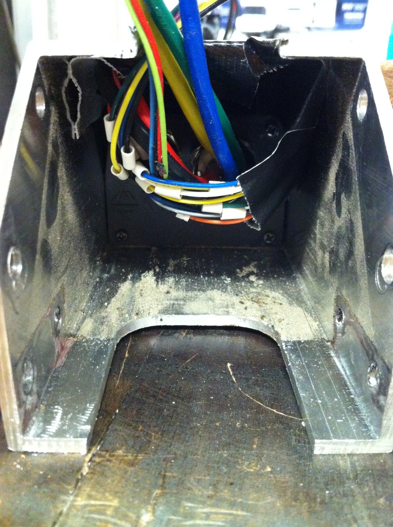
After a bit of testing, the cover is removed to check wire integrity. Note all the dust that the cover has successfully kept out. Plastic deformation of the bolt holes can also be seen.
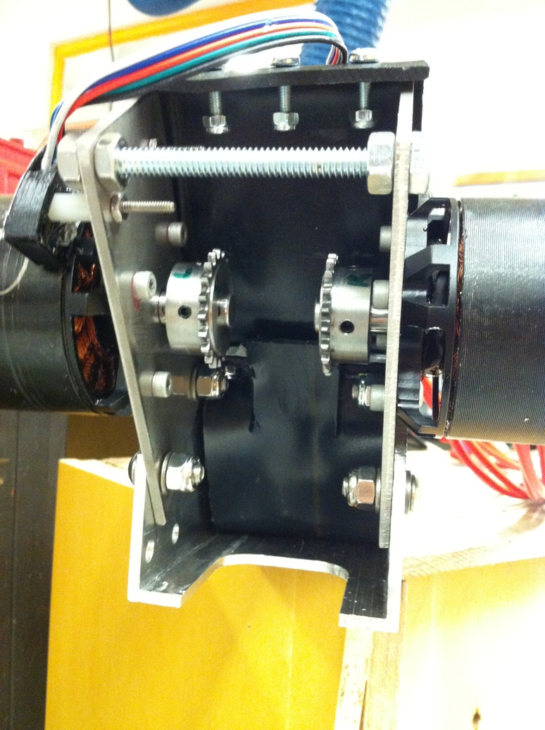
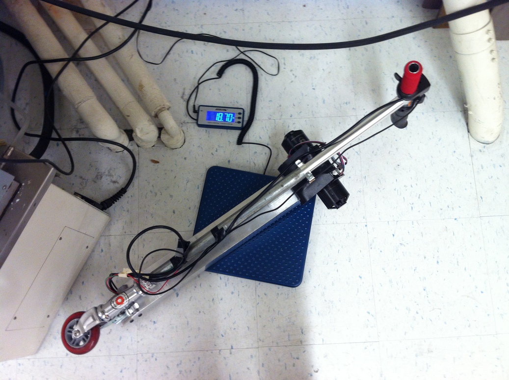
The end is in sight! The motors are then aligned so they appear to be a single motor to the controller. This is done by removing one of the roller chains, turning that motor's sprocket to a desired position, and then putting the chain back on. An oscilloscope is used to measure the phase difference, and the configuration with the least difference is picked. Then the two motor's wires are soldered to the controller in parallel. The completed scooter looks close enough to the CAD model, and weighs 18.7 lbs, not terribly light but acceptable given the increased power compared to electric scooters on the market (a quick Amazon search suggests this is actually on the low end of electric scooter weight, probably because I have excluded a number of 'comfort' features). The center of mass is towards the rear (because of the motors), but it is still straightforward to carry. One oversight is that with the plastic cover installed the handlebars don't fold down all the way - but this could be fixed by slightly moving the indents on the locking mechanism.
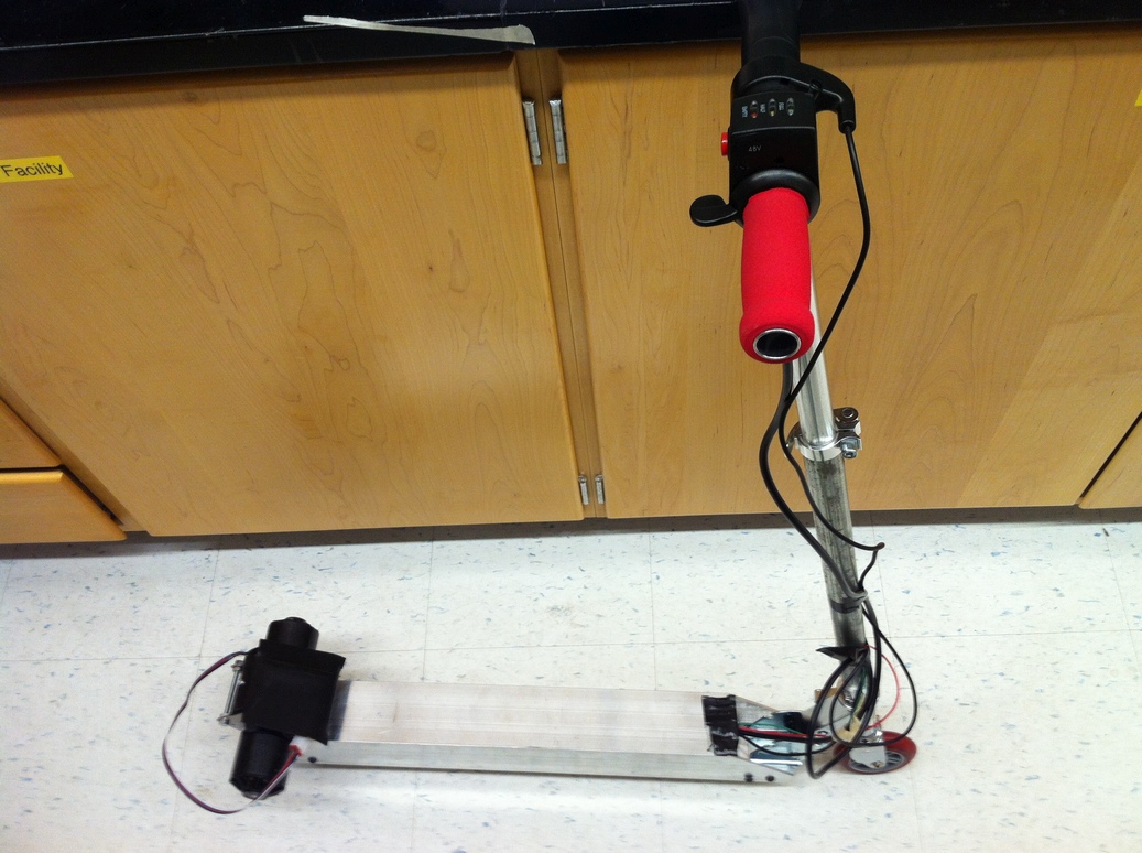
The scooter is complete!
First ride test! Note the front wheel coming off the ground from the acceleration.
Initially the regenerative braking was very rough - the throttle acted as an on/off switch going straight to 50% regenerative braking current when on. This caused quite a bit of wear on the back wheel, and was unacceptable for use on the road. In case you have a similar problem with a Kelly controller, the following seemed to help: setting maximum regen current to 50%, switch regen current to 5% (this should be the minimum current with lowest throttle input, but it doesn't seem to scale that way), and disabling the 'Smooth' setting. Enabling the 'ABS' setting helped get the braking working down to nearly-standstill speeds, whereas with ABS disabled the brakes cut off abruptly when a minimum (but still significant) speed is reached.
After about 5 miles of ride testing, a Lovejoy shaft coupling is added between the two motors, to ensure that they are always mechanically linked even if one of the roller chains breaks or comes loose while riding. The roller chain connecting link may come undone from hitting something or from vibration, or a loose chain may slip off a sprocket - and in the absence of any other coupling the two motors will get out of phase which will most likely lead to a serious accident. A less critical matter is that with a stretched chain the motors will tend to become out of phase when they are not driven, such as when coasting. This actually resulted in noticeable deceleration whenever the motors were powered off at speed.
Couplings were first milled down to fit in the space between the two motor sprockets, then bolt holes were drilled and countersunk to attach each coupling half to a corresponding sprocket. A 10 mm diameter rod was used to keep the sprocket and coupling centered during drilling while a vise was used to keep the two parts angularly aligned.
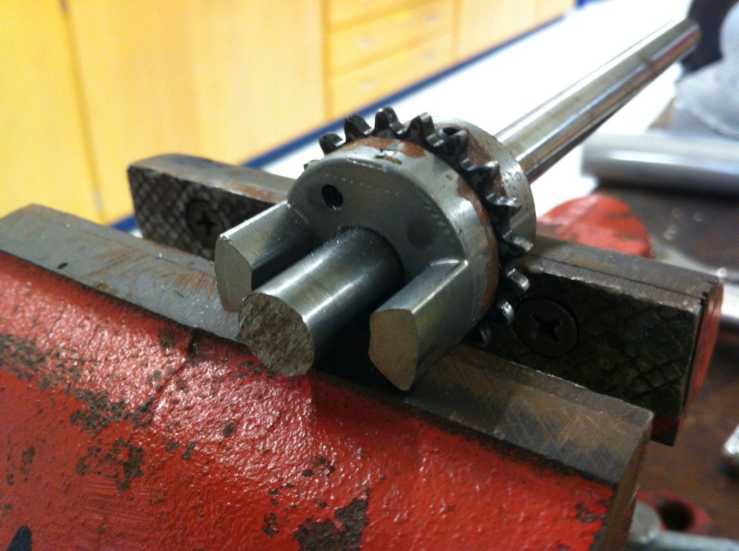
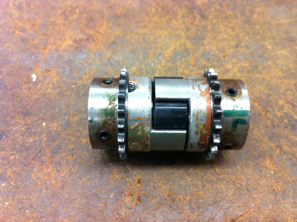
Drilling bolt holes in coupling and sprocket, then testing initial fit of both sprockets.
As a testament to this coupling being an afterthought, the diameter of the coupling was large enough to keep the chain from wrapping fully around the sprocket. The whole sprocket+coupling assembly was turned to decrease the coupling diameter closest to the sprocket teeth. This worked well enough though the delay due to machining was frustrating. Threadlock is then applied on the bolts holding the coupling to the sprockets.
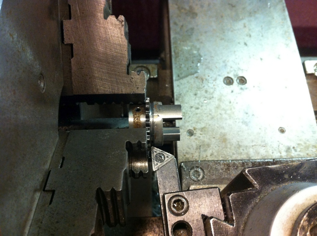
Reducing the diameter of the coupling on the lathe results in a successful fit of the chain. The angular alignment of the rotors is seen to be correct.
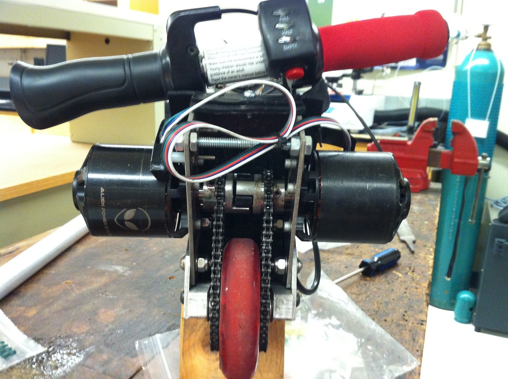
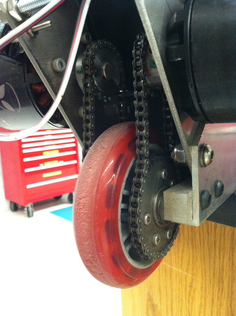
Now that the fit is confirmed, the motors are assembled once again and the scooter is ready for further testing. I also removed the rotor shells from the shafts and applied superglue to better secure the joint between shaft and rotor (because the fit between the shaft and rotor is very close, the glue layer becomes thin and its effective stiffness becomes surprisingly good). The testing revealed that the scooter now coasts for much longer, confirming the earlier prediction of deceleration mechanism with stretched chain. The alignment of the entire wheel and sprockets is now less critical. Overall I am happy with the addition of the coupling and would recommend it if you are in a similar situation.
It works! The first ride was a lot of fun. I had to learn to lean forward when accelerating and lean backward when braking, otherwise getting thrown off is easy. I reached ~15 mph without even getting to half throttle. I then wanted to see if the acceleration is still good when moving at speed - it is (and I had to apply a few bandages afterwards). The handlebars are almost comically small, which takes a while to get used to but helps highlight the absurdity of this project. The 2 ft long square tube, which I originally thought might be too long, is actually on the short side when the top chamfers are taken into account - I can only fit one foot along the tube, with the other positioned awkwardly across it - which again takes a while to get used to but is the outcome of making this almost as compact as possible.
After a ride around the block, I took apart the scooter to make sure everything was holding up and note any repair areas. The back wheel was definitely getting worn down (after riding, the wheel was very warm to the touch, while the chain was a bit warmer than ambient and the motors' temp increase was barely noticeable - which I guess means power (~100 watts?) is dissipated through deformation of the rubber in the wheel).
There is some wear on the rear wheel and the chain is noticeably loose. However the sprocket and wheel attachment seem to be just fine. Note the loosened bolts on the sprocket - this was due to insufficient threadlock.
The chain was noticeably stretched, requiring a re-adjustment after the ride. The easily adjustable motor mounts were definitely a good design choice. They are secured with locknuts, thus not requiring threadlock at each adjustment, and are designed to be easily moved without taking off any other components since the wrench can fit in the space between the chain and the tube side (exactly how it should have been designed).
For adjusting chain tension, a wrench is used to move the motors up or down. This can be done without removing any components, as the bolts are spaced such that the wrench can be easily inserted.
The electronics are also working properly. I checked whether the controller settings can be changed with the Kelly software without unplugging the battery or motors - it seems that this is the case (ie it never shorts out the battery when new settings are loaded - though you should test your controller with a power supply first and I would not recommend firmware updates with the battery connected). Knowing this has allowed me to leave the communication wires available on the outside of the frame so I can change settings without taking apart the scooter. The battery is permanently connected inside the scooter, so the only way to unplug it is to remove the electronics. So far this hasn't caused any issues, electronics-wise.
Electronics are partially removed to check insulation integrity.
Finally the scooter is re-assembled and charging is attempted for the first time. The batteries are charged with a lab power supply set to a maximum current of 1A (a slow charge - batteries can probably handle 50A) and maximum voltage of 49.2V (4.1V per cell, slightly less than 4.2V/cell LiPo maximum). (Update: continually charging to a lower voltage like this is not recommended, since balancing does not take place unless a battery is charged to its full voltage (here 50.4V) so the out-of-balance cells 'spill over'). No explosions yet! I won't know whether the BMS is working unless I take apart the electronics after a few weeks of riding. I think I'll just trust the manufacturer for now.
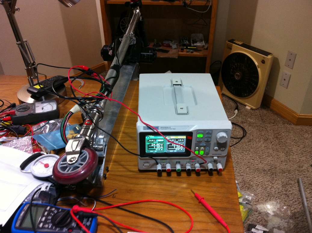
Charging the scooter with a variable power supply.
I rode the scooter another 5 miles without an issue (or a recharge). It is quite easy to use this as an unpowered kick scooter, and there is very little drag from motor 'cogging torque' when the scooter is unpowered - I can get nearly the same unpowered range as a regular kick scooter, so the friction in the transmission is at an acceptable level. There is significant wear on the rear wheel (the front wheel has negligible wear in comparison); the wheel becomes hot to the touch after riding indicating power losses. The wear must be due to the torque transmitted through the wheel along with more rapid compression cycling at high speed, as I did not observe similar wear when riding unpowered.
Rear wheel after riding approximately 10 miles. A lot of the outer rubber surface is lost compared to to initial appearance in the construction photos, and radial cracking has occurred.
After the coupling between motors was added, I took the scooter to rougher terrain. I was able to achieve approximately a 6 mile range using half battery charge at around 20 mph, which is more or less what I calculated in the spreadsheet above - so there is at least some empirical validation. The acceleration continues to impress me, and it is too tempting to go fast even though I ought to achieve a much better range at slower speeds. I still have not tested the top speed; I will try to find more protective gear before doing that (update: I completed a top speed test, see below). I expect it to be similar to the spreadsheet calculation - somewhere between 30 and 35 mph.
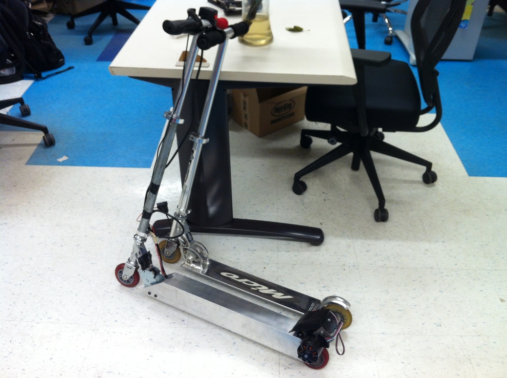
Comparison of the LiPo scooter to an unpowered kick scooter, showing the similar dimensions and appearance.
At this point I had ridden the scooter for approximately 15 miles, with satisfactory performance (no loose bolts or breaking parts). The only concern was the connection between the steering column and the front wheel - on large bumps (of which there are plenty on the road) the front wheel would tend to slip out of alignment with the handlebars (the connection is a friction fit), so it would be necessary to hold the handlebars slightly left or right just to go straight. To prevent a potentially serious misalignment while riding, I inserted a bolt radially through the steering column, ensuring a solid connection as opposed to the earlier friction fit (from the Razor scooter design). With this completed I felt confident enough with the controls and the mechanical aspects of the scooter to try a top speed test. With protective gear I took the scooter to full throttle on flat ground (on a low-wind day) and measured top speed using a handheld GPS. Top recorded speed over two runs (forward and back) was 30.1 and 30.2 mph - on the lower end of the expected range from the spreadsheet but still quite respectable for a 19 lb scooter with 90 mm wheels! (And recall that this scooter was not geared for speed, changing the gear ratio could probably get it up towards 40 mph). The battery was only half full at the beginning of the test, which implies the original estimate was reasonable.
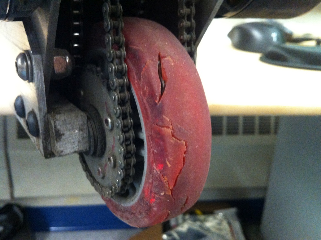
The rear wheel is significantly worn after about 20 miles of riding.
The most worn component is the rear wheel, which has developed extensive cracks around the perimeter and has started extruding black stringy plastic out through the cracks, which is somewhat visible in the image above. Likely the extrusion is due to high localized heating in the wheel from compression cycling melting the plastic combined with the pressure of riding pushing it outwards through the cracks like a liquid. The rubber section has become clearly 'flattened' and has expanded outwards axially beyond its original thickness, running into the roller chains on either side and eventually being trimmed by the fast moving chains. The front wheel, in comparison, shows negligible wear. I doubt this difference is solely due to weight distribution (because it is not that different), with the shear stress in the rear wheel when accelerating or braking contributing significantly to the wear. The chain stretches slightly but I have only needed to adjust the chain tension twice since it was installed so it appears acceptable. Surprisingly the chain still runs smooth and quiet despite the dirt from the road and the very high speeds I have subjected it to.