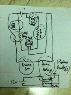
The circuit diagram contains an SCR in the middle, two relays, three switches, and two power sources, one for the latching circuit and another for the motor (these may be the same if your power source can handle the current load).
After the scooter was completed and worked properly with the aluminum contactor and 4AWG wires, I found it difficult to lock the scooter if I were to leave it in a public place. It would be necessary to disable the electronic system so a random person cannot start the motor, but with the existing setup the only way to do that would be to remove a wire from either the battery or the motor, which is far from ideal. Therefore I decided to go ahead and purchase a 100A rated contactor, and make an electronic circuit to enable the contactor only if a key switch had been toggled, thus giving an effect similar to key ignition in a car except it would be possible to remove the key after enabling the circuit.
The way this is meant to work is: upon walking to the scooter, set power switch to on, then insert the key to activate key switch, after which the motor activation switch (or lever) becomes active. Then it is possible to immediately remove the key and the motor will still function. After finishing the ride, set power switch to off, and then the motor activation switch is deactived until the key is inserted again with the power on. Consider the similarity to how a lawnmower works: there is a lever that must be held down for the engine to continue to run (equivalent to power switch) and then to start the lawnmower you need to pull a cord (equivalent to key switch). Another lever controls the drive on the lawnmower, which is equivalent to the motor activation switch mentioned above.
The circuit latches the system on/off. When circuit is 'on' the motor activation switch will turn on the contactor and thus supply power to the motor. When circuit is 'off' the motor will not be activated. To latch on, the power switch must be closed and the key switch must be closed. The key switch will connect the gate of an SCR which will latch on. To stay on, the power switch must remain closed (to keep current flowing through the SCR) but key switch can be open. The current from the SCR will activate a small relay, which will allow current to flow to the power contactor coil when the motor activation switch is closed. If the power switch is opened the SCR stops conducting and the small relay opens, thus no power is provided to the motor contactor regardless of the motor activation switch. The SCR will not conduct again until the key switch is activated and the power switch is closed. This prevents random people from turning on the motor while making it easy to activate/deactivate the motor.
The circuit diagram contains an SCR in the middle, two relays, three switches, and two power sources, one for the latching circuit and another for the motor (these may be the same if your power source can handle the current load).
Because of the use of relays in this circuit, it is important to install flyback diodes to suppress voltage spikes when the relays are deactivated. One of these diodes is shown in the diagram above, while the small relay does not have a diode since its current draw is small (although the diode would not be a bad idea, I was too lazy to install it and everything still works just fine). Additionally, since I bought a reasonably expensive 100A contactor for the motor, I wanted to ensure the motor would not destroy the contactor and thus I put a flyback diode on the motor (since it is an inductive load). This had some surprising consequences (see Results below).
First I soldered the circuit to a small PCB, and attached the power relay and key switch. Then I attached the power switch and motor activation switch to the circuit - these switches were installed on the scooter handlebars so they were attached after the key switch and relay were already installed in their final position inside the red box on the scooter.
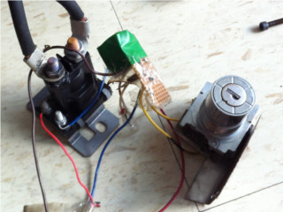
Left to right, the power relay, the latching circuit, and the key switch. The handlebar switches and battery power would be connected using the various wires coming from the circuit, while the motor would be connected to the thick black wires on top of the power relay.
Next all the components are installed inside the red box so they are not easily accessible from the outside (so it is not trivial to start the scooter without a key by shorting the wires), with a hole drilled for the key switch. The motor and battery are put in place and the scooter is ready for use. The tension-activated contactor from before is gone (replaced by the power contactor which fits nicely inside the red box, under the key switch) and the metal wire used to activate this contactor previously now has a spring placed on it for tension.
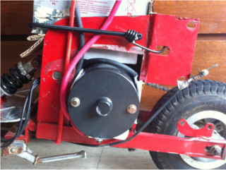
The key switch is installed and everything else is put in place. Note the small hole to the left of the motor - that is where the key is inserted to activate the scooter.
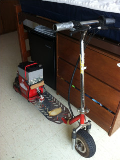
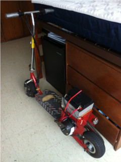
Side views of the scooter, from front and back. With all the control electronics fitting inside the red box, the outside of the scooter looks fairly neat. If there were a better way to attach the battery, it would even look professional.
The project worked as expected after some troubles. First, I tried using a different power source for the relay circuit so the large 12V battery would solely power the motor. This turned out to be a bad idea because the battery I used to keep the relay latched did not have enough current output for continued use, so the relay would unlatch after one activation of the motor, which made it quite annoying. Next I tried to connect the relay circuit to the 12V battery but with a capacitor and diode in series, which would theoretically provide current to the relay for some time if all of the battery's current goes into the motor. This also proved to be a bad idea because the diode creates a voltage drop, and thus the relay which expected 12V would randomly open and stop the motor unexpectedly. At some point it even created a resonance and rapidly switched the motor relay on/off as the voltage drop was overtaken by the voltage increase on the battery after the motor was switched off. This is of course bad for the motor relay. To remedy this issue I simply got rid of the capacitor/diode interface and connected the relay circuit directly to the 12V motor battery. It worked exactly as expected, even though the motor drew pretty much all of the current from the battery, I guess because the relay coil is effectively a short circuit so some current will flow through it no matter what. In other words, to prevent frustration either use a good separate power source for the relay circuit, or connect it directly to the main battery.
The next trouble came up during a ride when I heard a loud 'pop' and saw smoke coming out of the red box. The scooter still worked so I assumed it was the flyback diodes on the motor, which were meant to protect the power contactor from arcs. Turns out I was wrong - it was actually the wires connecting the diodes to the motor. Once again I used the dreaded 2 AC cable configuration (which made a complete mess of my very first trial run), which I assumed would be adequate since the only energy the diodes would have to dissipate is that of the arc, however I was clearly wrong. The diodes still work fine because they are each rated for 100A, but the wires are done for.
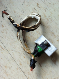
The melted wires connecting the two flyback diodes to the motor. The diodes are fine thanks to the large aluminum heatsink (there is one diode on each side of the heatsink).
I kept riding after the smoke incident without taking apart the scooter because it took me so long to put it together and it still worked. I expected it to fail eventually, and so it did. In fact the power relay melted due to a high current load, however I am not sure what to attribute the failure to. The flyback diodes still worked and the wires were functional, despite looking bad, so they should have still protected the contactor from arcs. On taking the contactor apart, there were clear arc spots on the contacts so arcs still occurred, which through testing I found could have been due to high initial currents rather than flyback currents (which the diodes should have suppressed). Nonetheless the constant current draw should not have exceeded 100A, so either the relay is not rated properly or the motor is not rated properly. In any case, I will need to look into other control options (probably solid state contactors) for the scooter to be a reliable machine. However I am not sure if I want to spend the extra $200 or so to make it functional. It was fun to ride for a while, and now that the concept has been proven the high-powered electric scooter will probably go on a temporary hiatus.
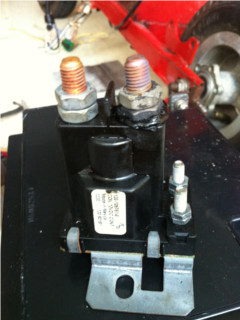
The failed power contactor that controls the power to the motor. Note the melted plastic under the bolt on the right.