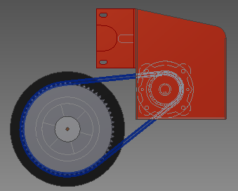
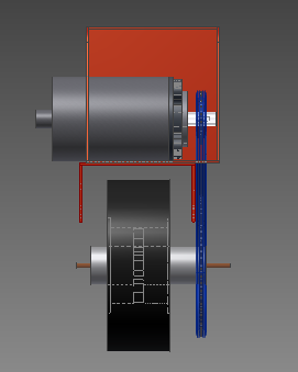
These images were created using Autodesk Inventor 2012, and contain a to-scale model of the expected scooter wheel/motor setup. The first image is a view of the motor and wheel from the right while the second image is a view from the top.
After my bike was stolen, as a matter of necessity for transportation it was decided that a Razor scooter would act as a temporary way of getting around. However after a few days of experimentation it became evident that the small wheels were having a hard time with concrete sidewalk surfaces and that the scooter needed overall more power. Gas motors are loud and not environmentally friendly, so an electric design was chosen. After coming up on a bargain for an old electric scooter chassis the project finally got a head start. 'All' that would need to be done is to obtain a motor, battery, electrical control components, chain drive components, and motor mount; additionally some clean-up of the body and adding lubrication to moving parts was in order.
These images were created using Autodesk Inventor 2012, and contain a to-scale model of the expected scooter wheel/motor setup. The first image is a view of the motor and wheel from the right while the second image is a view from the top.
When I got the scooter chassis I thought getting the motor on would be an easy task, but it really was not. I learned some very important lessons while working on this project which I would like to mention first:
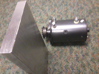
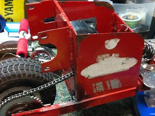
The first order of business was to figure out where on the scooter the motor would go. My original idea was to put it in the same place as the old motor (the brackets visible above the back wheel in the model). However, the motor was too large in both diameter and length to fit there. Thus the first lesson above. I thought the next best thing to be placing it on top of the brackets, and creating an aluminum holder to attach it to the brackets under it. I ordered the aluminum piece and later realized that this is a really stupid place for a motor since all the torque would effectively be transferred to an unsupported piece of metal, and doing so would require a long chain to function. Also, the motor would have no protection from the outside, and there would be an awkward space in the red box.
The initial idea was to place the motor on top of the red brackets and hold it in place using the piece of aluminum visible towards the left in each image. This was decided to be a stupid idea and luckily I had not done any machining on the aluminum piece by then.
Finally I decided on the current design (see model drawings above), where the motor is placed inside the red box and a chain comes out to the wheel sprocket. I was hesitant about this design because it would require a lot of cutting of steel, and would make the motor difficult to install (though similarly difficult to steal).
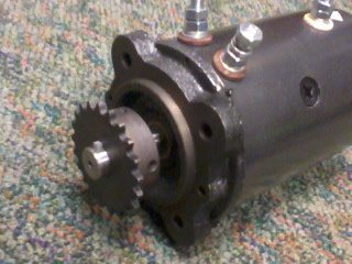
Once the design was loaded on the computer model, I tried to figure out the best way to implement it with the aluminum piece meant to hold the motor in a different position. I ended up cutting the aluminum rectangle into two squares, and making one square the motor holder, and the other square the top cover for the motor holder. The aluminum is 1 inch thick and holds the motor about 0.5 inches inward, giving sufficient grip strength to handle the 2HP motor. The through-holes for the motor shaft and sprocket, as well as the bolts, were cut using a water jet, while the shape of the outside of the motor was milled out to 0.5 inches depth in order to provide radial stabilization while the bolts kept the motor mounted (linearly) to the holder. The motor accepts four bolts, and has a pattern on its face that could be placed in a milled-out holder and used to prevent the motor from turning within the holder. The bolts would also do the job but having a half-inch of aluminum surrounding the motor would provide much more force to resist the motor turning. This aspect is quite important because it is how the motor will accelerate the scooter - it will try to make the motor mount turn and the motor mount will have to handle the full torque of the motor so the wheel turns instead of the motor mount.
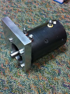
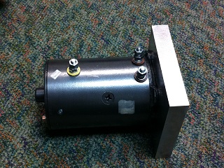
Two views of the machined motor mount, which is made from half of the aluminum block seen above. The motor is bolted 0.5 inches inside the block.
Next all bolt holes were countersunk so the bolts would not interfere with the chain on the motor holder, and would not disturb the battery resting on the top cover. A hole in one side of the motor holder was drilled and tapped to accept the top cover aluminum piece. The top cover had a groove milled in it to be aligned in a perpendicular fashion with the motor holder, in order to prevent the holder from rotating radially about the vertical axis. The fit of the motor holder in the box and the weight of the battery on top of the top cover would prevent the motor holder from rotating about the horizontal (shaft) axis. The location of the groove in the top plate would keep the motor sprocket aligned with the wheel sprocket so the chain would not be forced to curve.
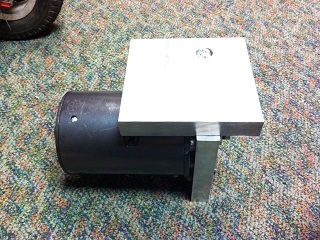
The motor holder and the top cover are attached to the motor. This will be assembled inside the red box on the scooter chassis once holes for the motor and the chain are made in the box.
A 21-tooth sprocket is attached to the motor shaft to transmit torque to #35 chain which will go to the back wheel of the scooter. This required the use of a Woodruff Key which I made out of 0.2 inch thick aluminum using a water jet cutter. It fits nicely and has worked fine so far.
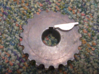
On the left is the motor sprocket, with the key to connect it to the motor shaft lying on top. On the right, the key and sprocket are attached to the shaft.
There was a sprocket originally installed on the scooter chassis, which turned out to not match #35 chain. The sprocket was in fact to some metric specification. Thus I ordered a new sprocket for #35 chain and the smallest one I could find which matched the bore on the wheel was a 60-tooth sprocket. Taking apart the ball bearing holding the sprocket (a one-way bearing, like what is used on bikes to allow going forward without spinning the pedals) required a lot of patience. To put the balls back in place I bent a piece of notecard paper into a roll to precisely fit the outer edge of the bearing and keep the balls from rolling inside.
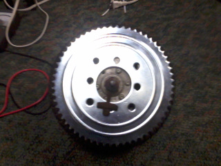
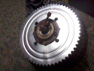
The 60-tooth sprocket, on left before being installed on the ball bearing, and on right after.
As may be visible from the photo above and from the model image, the bearing is not very far off the ground compared to the wheel. When the chain is added in, this distance decreases even more. Also visible from the model is the distance between the side of the tire and the sprocket, which essentially means that leaning into a turn would be impossible to do with this size sprocket. Thus I would not be able to safely go fast on the scooter. In practice this made it difficult even on slow turns, as I would hear the sprocket scratching the ground when testing the scooter using manual propulsion. Therefore a new sprocket was needed and the dreaded ball bearing would have to come apart again (this time I made use of it by cleaning and lubricating the inside). A 40-tooth sprocket was purchased and needed to be machined to the right bore and to accept the four bolts holding it on the bearing. The results were very good.
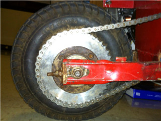
The 40-tooth sprocket used in the final design, shown with chain installed.
This was a fairly obvious component but there were challenges that are worth mentioning. The first challenge was determining the chain position. This was important for my design since I needed to drill holes for the chain in the motor box, and did not want the chain to be touching the edges of those holes. After installing the motor sprocket and motor holder in their final positions in the motor box, I used string and magnets to try and visually determine the chain position by drawing a string with an attached magnet from the motor sprocket, and another string with a magnet from the wheel sprocket. The magnets did not affect each other through the steel side of the box, but nonetheless they were useful for keeping the strings at proper tension. This visual analysis worked sufficiently well although expansion of the drilled holes was required to fit the actual position of the chain.
The second challenge was determining the chain length. Once the holes for the chain were drilled and both sprockets were in their final position, I passed the chain (I bought a 10-ft length) through the system and marked where it would need to be cut. Luckily the back wheel can move linearly which can be used to adjust the chain tension - this is very important because a chain will stretch during use and will require adjustments unless you are using a tensioner (such as the spring-loaded assembly in a bicycle). Additionally, I had extra connecting links and cut the chain in a way that would provide 7 different sequential combinations, thus even if I made an error there would be a way to properly close the loop. The error would be in cutting too short of a length, so start with a longer length if you are unsure. Cutting the chain involves breaking a link by pushing out the connecting metal rod between two links, pushing in a direction perpendicular to the plane in which the chain bends around a sprocket. This can be done using a special tool, a press and a small bolt, or a hammer and a punch (with a nut placed under the link for support, to prevent bent edges). Before breaking a link, make sure the connecting piece you have will fit on the resulting chain - a master link will only work properly half of the time while the other half you will need a half-link.
The chain is installed to connect the motor and wheel sprockets.
This was the single most significant source of frustration in this project, because I have never dealt with large currents before and apparently it is quite expensive. My advice would be to go for a higher voltage motor with less current requirements (power=current*voltage) if you are building something similar, because new semiconductor devices can control relatively high voltages while controlling high currents requires physically big structures which are not common and thus quite expensive.
So, now that the motor is mounted, the sprockets are in place and the chain is properly adjusted, all that is necessary is to turn the motor on and the scooter is ready! Yet this is exactly the challenge, how to supply the 1200w the motor is expected to draw, and more significantly how to control the power, ie turn the motor on and off (as certainly would be useful during trips). There are golf cart controllers that claim to handle the current, but they are quite expensive, more expensive than the combined costs of everything else including the battery and motor. I bought a controller from motiondynamics, who offer very good deals on controllers in terms of dollars per amp. I got the 100-amp controller model, yet it easily overheated when powering the motor (and not the MOSFETs as I would have expected, but rather the clamping diodes), so it is quite likely that the motor is drawing well in excess of 100 amps. This high current draw is also evident by its significant heating up of wires rated for 140 amps, so I will not make any claim as to the quality of the motor controller, other than it survived running the motor until I realized that the diodes were burning hot, and still works now to power smaller motors. Ultimately, a contactor based system was deemed necessary to allow full and unlimited power output, which was the whole purpose of this project. Once again the current problem persisted, and all the high-current (100A+) contactors I could find online were prohibitively expensive. Thus I decided to make my own, consisting of two bolts and a piece of aluminum that would be drawn against them using one of the brake cables on the scooter, and this piece of aluminum would conduct electricity from one bolt to the other when it is touching. Strong springs would force the aluminum piece off the bolts when the brake cable is released, thus ensuring my safety in being able to turn off the motor when necessary. This is an important point because if the contactor is not well designed the metal pieces may get melted onto each other due to high current and subsequently would be impossible to separate, and this would be quite dangerous since the scooter would be unable to stop (turns out the motor is more powerful than the brake force of the disc brake on the scooter, so this is indeed significant).
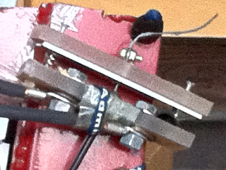
The contactor for the motor on/off control is activated by using the back brake cable, while the front brake cable activates as the actual brake. The aluminum plate on top is brought down onto the two bolts on the bottom and conducts electricity between them. The springs on the sides of the bolts are strong enough to keep the aluminum plate from sticking to the bolts under high current loads.
With the contactor providing a sufficient solution for motor control, the wiring became the next issue. Any wire I would put to connect the motor to the battery would overheat almost immediately. The thickest wires I could find were AC wires such as used for lamps, TVs, etc. I ended up using four wires in parallel for each connection point (two wires in each AC cable, and two cables between each connection) between the motor, contactor, and battery. This seemed to handle the currents until I actually went out for a ride. The ride was much shorter than expected due to the wires melting over the course of the ride.
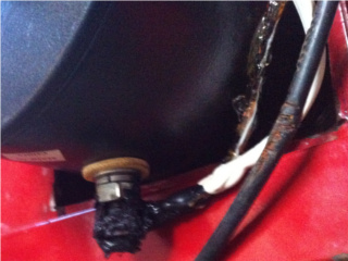
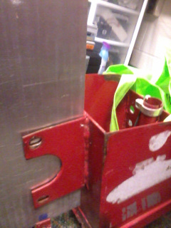
The wiring involved 2 AC cables in parallel between every contact point, yet the wires melted under the high current load as evident from these photos. It also looked messy with so many wires.
Clearly a better solution was necessary. I purchased 4 AWG cables which were rated for at least 100 amps, and corresponding crimp connectors so the cables could be neatly and properly connected to the electric components. While waiting for the wires to arrive, I took apart the motor and cleaned the commutator and brushes, and lowered the pressure on the brushes which was insanely high initially (so high as to create a heat load due to friction against the rotor). Also I ran the motor under no load a few times to allow it to "break in" (this was done for short periods of time because apparently series-wound motors such as the one I am using can spin up too fast under no load and self-destruct).
Once the wires arrived, actually crimping the connectors required the use of a press since pliers were nearly useless on a block of metal that would fit a 4 AWG wire inside. All the crimps were soldered from the end also to ensure full electrical connectivity. The new wires made a huge difference in performance and could be used continuously (at this point the contactor was the limiting component since it would overheat greatly from the current load, yet due to its basic construction it did not fail). With the ability for continuous (although quite hot) usage I considered the project a success and this is how it appears today.
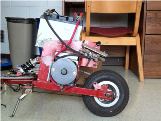
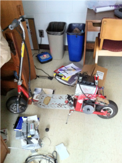
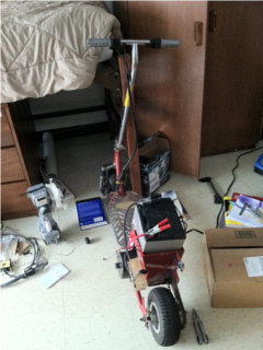
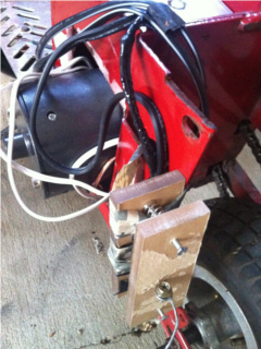
The completed scooter project, on left a close-up of the new wires, while in middle and on right there are views of the entire scooter assembly. The clamps on the battery are connections to the battery charger.
Overall, the project was a learning experience. It was probably the most frustrating project I've done, if only because of its size and expense, however in the end it worked successfully and it is very fun to ride. The powerful motor makes itself clearly felt when accelerating, however the top speed is not terribly fast, topping out at 25 mph. This is less than the expected 35mph according to online specifications on motor RPM, but the measurement specified online was taken under no load. In any case, doubling the voltage would double the RPM and top speed, but I think at least for now the top speed is fast enough so it is not dangerous to ride around (the maneuverability quickly goes down with high speeds due to the difficulty of steering through the small front wheel).
The scooter has taken on some relatively tough hills (on paved roads) although it is probably geared too high (1:2) to do so efficiently. Thus the motor heats up considerably when going up hill, but it is able to go up nonetheless. I do not want to try really tough hills for some time because I would not like to destroy the motor quite yet. On flat ground, and especially downhill, the scooter accelerates appreciably fast as mentioned earlier. The scooter chassis has front and rear suspension so the ride is smooth. If the electric system fails, it is possible to ride around manually, although it is not very comfortable because of the height of the platform.
New: video of a ride on the scooter, from the viewpoint of the front wheel taken using my cell phone. The quality is not great because the wheel vibrates quite a bit, and also sideways on Windows Media Player for some reason, but the video gives an idea of the speeds attainable with this scooter. It starts off with me pushing the scooter, then electric motor accelerating to an intermediate speed (will be audible), and after I pass the police car and cones it is taken up to full speed. Download ride.mov.