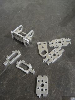
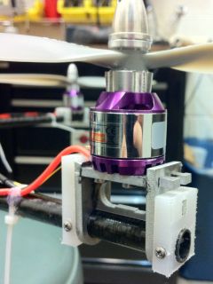
Construction of the motor holders from an aluminum sheet. Parts are cut out using a waterjet, then epoxied together, then attached to carbon fiber rod using plastic spacers.
The unfortunate crash that rendered the aluminum frame quadcopter inoperable led to the idea for this project. After the difficulty of constructing the aluminum frame and the general flimsiness of that frame in certain axes, I decided to try a carbon fiber frame design. Multiple other lessons from the aluminum frame were taken into account and overall the parts were designed to be easier to machine and assemble. Most of the aerodynamic parameters (propeller size/speed, weight, aircraft size) were kept the same due to sufficient lift/flight time in tests, and all the electronic components were re-used from the aluminum frame, providing a comfortable level of constraints to allow focus specifically on the frame design.
The size of the propellers set an approximate minimum distance to be kept in the frame. For a good camera attachment, I wanted to maintain the general electronics base concept from the aluminum frame, meaning the carbon fiber beams would each need to be about 12 inches long, as before. A major problem with the aluminum frame was the wobbly nature of the central beam supports, causing movement of the frame elements. To avoid this outcome as much as possible, it was decided to have two 24-inch beams rather than four 12-inch ones, so that the central element would only need to hold the beams at a 90 degree angle rather than also transmit bending forces from one beam to another. This introduces the issue that the two beams would be at a different vertical level, causing height differences in the propeller level. This effect is removed by the use of different height motor mounts for the two beams.
Performing some stress calculations, and allowing for the reaching of the 2000 g weight limit, a 0.45-inch carbon fiber tube was selected for the two beams, and an ABS plastic piece for the central support. Unlike the aluminum I-beam, the round tube transmits bending forces equally well in any direction and can handle torsion successfully. Despite the higher strength/weight ratio of carbon fiber compared to aluminum, the final carbon fiber frame design was heavier than the aluminum frame to allow larger margins for crash impacts, since the weight limit allowed such an increase.
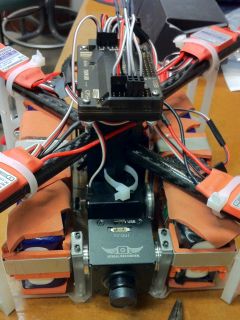
The angled plastic base supports were removed and replaced with straight plastic supports of much larger cross-section. The APM controller was mounted on the top of the quadcopter to allow for easy USB programming and connecting peripherals. Vibration mounting pads were placed on all bolt connections to the electronics base and to the APM. The central frame holder which supported the two beams was lengthened so it could be attached to the electronics base, providing an important central point of support in addition to the four corners handled by the plastic supports; this allowed the plastic-beam framework of the aluminum model to be removed. Bent sheet metal parts were designed to hold the batteries and the APM in appropriate locations, while drill holes were added to the CAD model to attach other electronic components and wires. Clearances to sheet metal parts were added to allow inclusion of protective foam (one should have a healthy fear of LiPo batteries near sharp/metal edges) and vibration isolating rubber. A design of the motor mounts, requiring multiple interlocking aluminum pieces, completed the frame.
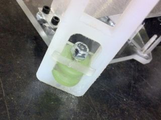
The project started out with waterjet cut pieces for the motor holders and plastic supports. The aluminum motor holder pieces were cut with a tab left to prevent them from falling into the waterjet, which was taken off with a bench grinder (note that grinding aluminum should be done on a separate wheel as the aluminum will stick to it unlike steel). Next the central support piece was milled out, with holes to accept the two carbon fiber rods and perpendicular holes for bolts that would hold the rods in place, as well as a few weight-reduction holes. The motor holders were assembled and held together with JB-Weld epoxy compound. Note the way they were designed, so that even if the epoxy failed it would be quite difficult for the motor to fly off.
Construction of the motor holders from an aluminum sheet. Parts are cut out using a waterjet, then epoxied together, then attached to carbon fiber rod using plastic spacers.
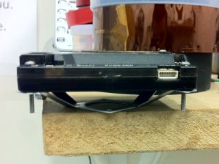
The APM mount was made out of a thinner aluminum sheet and bent into shape. The APM board is drilled through in four corners to allow bolting to the mount. Note that without additional support inside the plastic case, the APM board is likely to shift during flight.
The 60-inch carbon fiber rod was cut into two 24-inch long rods using a hacksaw with the cut locations taped over beforehand to prevent fraying of the carbon fiber threads. (The rest of the rod was used as a destructive stress test piece which showed the impressive strength of carbon fiber). The holes for all bolt connections were drilled with the two rods side-by-side to ensure the same dimensions on the two beams. These holes determine the spacing along the length of the rod, that is the midpoint where both will be connected to the central support, and the length from the center at which the motors will be placed. The holes were drilled in the horizontal direction on the tube, since vertical forces in a beam are handled by the top/bottom parts of the beam more so than by left/right sections (which is why an I-beam is effective in one direction and not in the perpendicular). Drilling the holes vertically would break carbon fiber connections in the layers which are most useful in handling the vertical loads. It was assumed that the vertical loads would be higher than horizontal loads, thus the holes were drilled in a horizontal direction perpendicular to the rods. Prior to drilling, all hole locations were taped over, for the same reason as in the sawing operation.
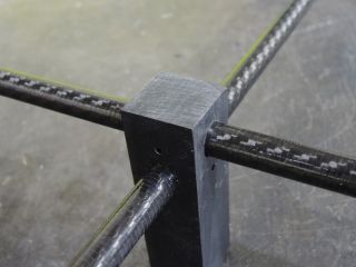
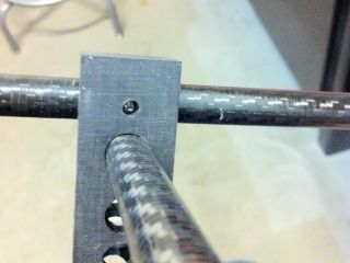
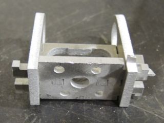
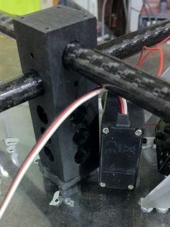
Construction of the central plastic support and attachment of carbon fiber rods. The rods are bolted to the plastic support with the bolt perpendicular to the primary load direction (vertical load -> horizontal bolt).

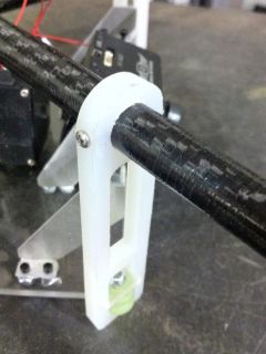
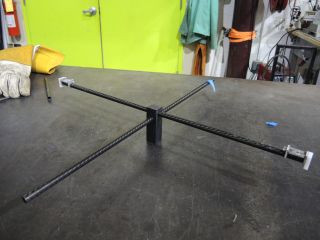
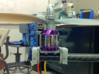
A test assembly of the frame components. All connections to the carbon fiber rod are bolted for increased rigidity.
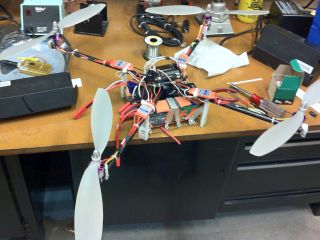
The electronics were then laid out on the acrylic base sheet (cut with a waterjet - a laser cutter is a much better choice for brittle materials like this). The camera was mounted to the base and attached to a servo to allow changing its angle.
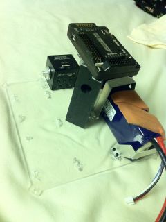
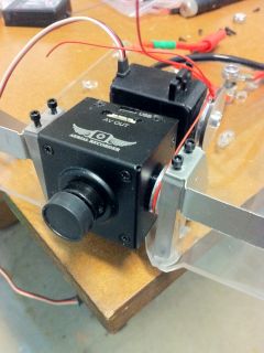
Laying out the electronics on the acrylic base, and attaching the camera. The battery supports are oversized to allow inclusion of protective foam (since pierced LiPo batteries are dangerous).
Vibration insulating pads were added on both sides of bolted connections for the central support and each of the four corner supports, after which all the frame parts were bolted together. The holes in plastic parts were drilled undersized for the bolt and left untapped, thus forcing the bolt to create a thread and leaving a sufficient amount of friction to prevent the bolt from rotating during flight without requiring further measures like locknuts or threadlock.
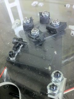
Vibration isolating pads are attached on both sides of all relevant bolted connections.
The motors were attached to the motor holders using threadlocked bolts, and the propellers were attached to the motors using fine grit sandpaper glued to either side of the propeller adaptor to prevent slipping of the propeller against a smooth metal surface. Threadlock was also used on the adaptor threaded shaft. Lines were marked on each propeller and adaptor pair in order to allow easy checking of whether propellers have come loose (that is, if the mark on the propeller does not line up with the mark on the adaptor then something has slipped after assembly). Similar lines were drawn across all the heads of bolts attaching the motors to the frame for easy pre-flight inspections. A thin layer of hot glue was placed across bolt heads that were not flight-critical as a measure to keep them from spinning and an indicator of whether they had moved after assembly.
Propellers attached with hot glue or sandpaper to provide friction sometimes experience slip. The open surfaces of the motor mounts as seen here also act as an effective heatsink for the motors, an unintended but beneficial side effect.
This method showed that the sandpaper and glue combination was insufficient to hold the propellers in place during crash landings, and for that reason a wire was soldered in place to hold each propeller adaptor's top to the motor. Thus even if the propeller slips or the adaptor comes loose, the wire will prevent either one from coming off entirely and will not allow the propeller to slip very far. If using similar propeller adaptors, this method is recommended to increase safety and reliability of the aircraft.
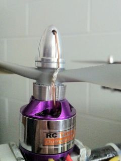
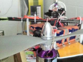
A wire is passed through the motor and propeller adaptor to ensure the propeller cannot fly off or slip. The wire is soldered together so it cannot break loose.
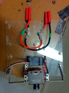
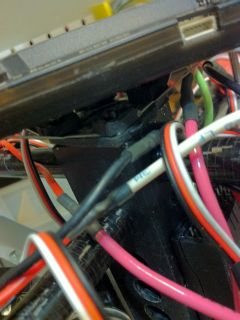
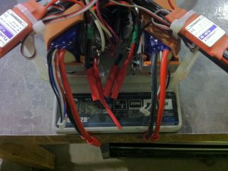
All the electronics, including batteries, were bolted into place on the electronics base board. Zip ties were still used to attach the ESCs (motor controllers) to the carbon fiber tubes. Placement on the tubes allows for better cooling of the ESCs in flight, as they get quite warm due to the current draw. Inadvertently, the aluminum motor mounts act as an effective heatsink for the motors, which get hot during flight (hot enough that I worried about de-magnetization, but no effects have been observed after more than ten flights). For designs in which a high power density is expected in the motors, perhaps some more thought regarding the heat sink capability of motor mounts would be worthwhile. The bolt/crimp connector system used for connecting all high-current wires was kept from the previous design.
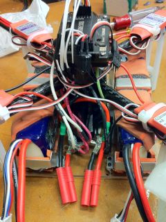
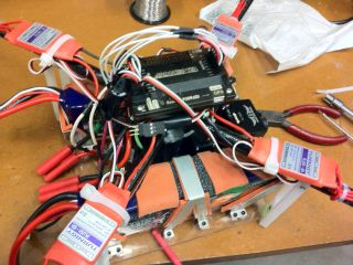
Electronics are attached to the board with minimal reliance on zip ties.
The finished quadcopter, with electronics and all mechanical parts attached and ready for flight. Weighing in at 1955 grams (expected design limit 2000 grams).
An important difference between this project and the aluminum frame is in the tuning that was performed before the first flight. Tuning the aircraft involves adjusting PID variables (or some subset of these) for the onboard flight stabilizing controller. The flight controller accepts stick movements from the RC system, corresponding to the pilot's commands, and adjusts each of the four motors depending on the aircraft's movements.
There are different extents to which the flight controller makes flying easier for the pilot. The APM and other advanced controllers support an easy flying mode, where all movements are changed to be from the pilot's perspective - that is, pushing forward on the pitch control will move the quadcopter away from the pilot no matter where it is. This requires both a compass and a GPS onboard.
Removing the perspective component results in a 'stabilize' mode, where a centered pitch and roll stick input means the quadcopter should remain level (parallel to ground plane). This requires a gyroscope in three axes and an accelerometer in three axes. Note that cheaper controllers may support the stabilize mode without the accelerometers, by integrating the gyroscope outputs to obtain a measure of total angular displacement. If this is the case, a gust of wind or rapid acceleration may cause the controller to leave the aircarft at a considerable tilt when the pilot expects it to be level, and this generally cannot be fixed until the aircraft is landed.
Removing the stabilization component results in a difficult flying mode, called 'acro' on the APM due to the ability to perform aerobatic maneuvers in this mode that are not possible with the stabilizing feature (such as flips). In this mode, a centered pitch and roll stick input means the quadcopter will maintain its current pitch and roll; movement of the stick from center will cause acceleration about the corresponding axis. This can be successfully done with only gyroscope sensors onboard.
The most difficult mode is where the pilot controls the motors directly, but I am not sure this is even practical. In this case a flight controller is not needed.
For this project I decided to use the stabilize mode. The easy flight mode seemed to put too much control onboard and would not be sufficient for teaching me to pilot the aircraft.
All the uses of the flight controller, including acro, require tuning. Tuning is the process of adjusting the controller's response to inputs from (specifically) the gyroscope sensors and the pilot's commands. In simple terms, tuning matches the mathematical response of the flight controller to the aerodynamic/mechanical response of the actual aircraft. If the quadcopter is small with very powerful motors, the flight controller will need to send very slight corrections to maintain a certain orientation and not overshoot it, whereas if the quadcopter is large with underpowered motors, the flight controller will need to send large corrections to prevent the quadcopter from turning to an angle from which it cannot recover.
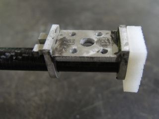
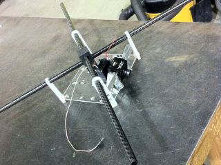
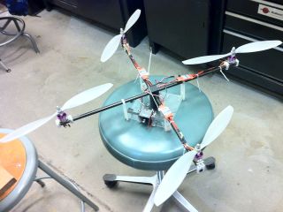
For tuning this model, I arranged a small test rig that would allow the quadcopter to tilt along an axis but not move laterally. This was done by passing a string through one of the carbon fiber rods, and using this string to hold the quadcopter so it would not touch nearby objects. With the size of the propellers on this model, that was fairly scary to stand near so I passed a second rope through the other carbon fiber rod just to make sure this would not hit anything. With a smaller quadcopter the tuning process might be done by just holding it in one's hand.
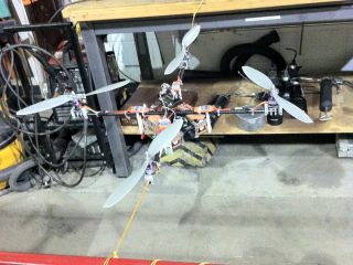
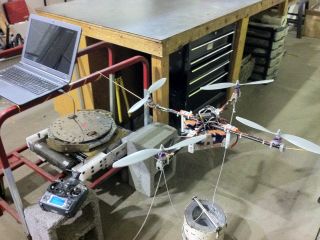
The test rig is shown here with the quadcopter supported entirely by strings.
Before starting tuning, ensure everything on the quadcopter is in its final location and no components will be added/removed for actual flight. To get a good level of settings on a test rig, the following tuning guide is recommended: http://diydrones.com/forum/topics/arducopter-tuning-guide
In my experience, while this approach tunes the settings enough for a controllable first flight, it is very important to re-adjust the settings with in-flight testing, using the settings from the test rig as a starting point. Without any tuning, the quadcopter will likely not be able to reach more than 1-2 feet and will have a tendency to crash.
The following guide describes the approach I used for in-flight tuning of the controller, which resulted in very stable flight. The APM can be set to use a knob on the transmitter to vary one of the PID parameters in-flight, using the 'Ch6 Opt' setting in Mission Planner. Additionally, the measured angle and desired angle can be logged in-flight along with the parameter that is being varied (the logs of interest are ATTITUDE_FAST, MOTORS, and PID, and need to be enabled through Mission Planner). By plotting the logs after each flight, it is possible to determine the optimal value with much more certainty than is possible from just observing the quadcopter in flight. The guide is APM-specific but the general principles can be applied to other controllers.
First though, it is important to know what the parameters are. Stabilize P, or Stab_P, is a parameter used only in stabilize mode and determines how aggressively the controller will try to maintain the pitch/roll angle that is requested by the pilot - if this is too low the stabilize mode tends to act like acro mode and is difficult to control, and if it is too high the quadcopter will oscillate about the desired angle about 1-2 times per second. Rate roll/pitch P, or Rate_P is telling the controller with what level it should respond to a certain rate of rotation - if it is too low, the pilot's inputs will have little effect and the quadcopter will be uncontrollable, if it is too high the quadcopter will react aggressively even to small stick movements and will likely oscillate 1-2 times per second. Rate_I is an integral term, and is approximately how much the controller will respond to overall rotation (angular changes) - meaning if set correctly this term will tend to correct small deviations that Rate_P will ignore, while if set too high it will cause large and slow oscillations (less than 1 per second) leading to loss of control. Rate_D is the derivative term, and responds to the change in rate of rotation - when set correctly it can enable a fast response by Rate_P without causing an overshoot condition, but if it is too high the quadcopter will oscillate at a very fast rate of a few (3-5) times per second (that will be audible from the motors changing frequency even if it is too fast to be visible).
Because the various parameters can induce oscillations on various timescales, I have found that logging the quadcopter's angle and desired angle, along with PID terms used during flight, proved to be more helpful in tuning than simple visual observation. If your controller supports logging, I would strongly advise using that feature for tuning. Otherwise, you might not get peak performance but the method below will still get your aircraft stable.
For the procedure below, it will be useful to refer to the chart below. There are many PID guides but I found this one to be easily understandable and an accurate representation of a typical quadcopter response.
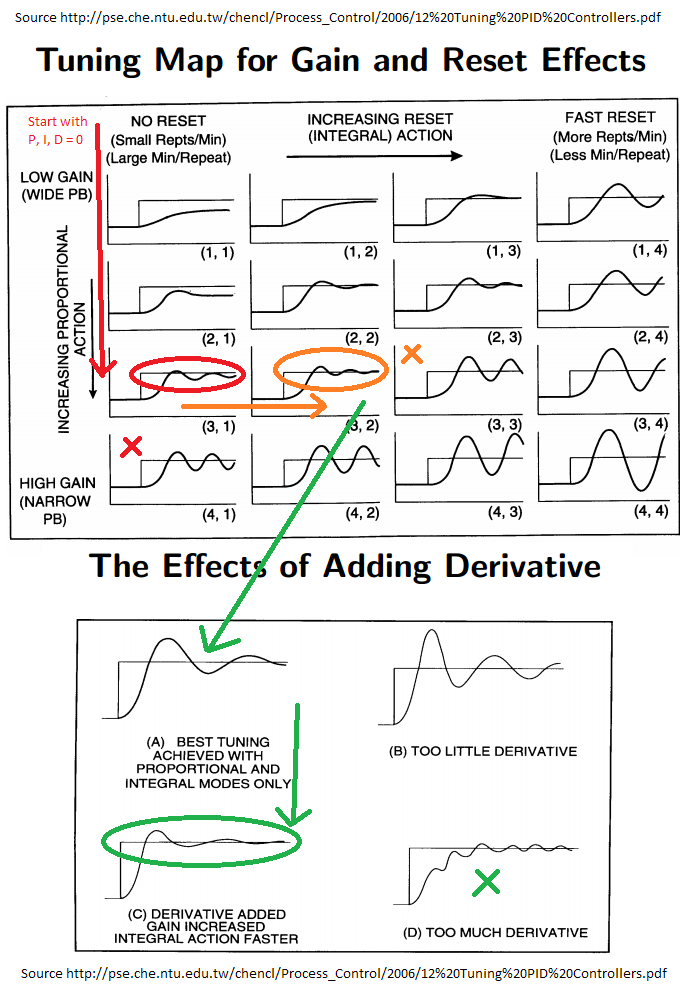
A guide for tuning the PID parameters on a quadcopter. Source: http://pse.che.ntu.edu.tw/chencl/Process_Control/2006/12%20Tuning%20PID%20Controllers.pdf
Tune the quadcopter in stabilize mode. Start with an initial Stab_P and Rate_P as determined from a test rig setup. My starting values were Rate_P = 0.204, Stab_P = 3.6. The other parameters, Rate_I and Rate_D should both be set to zero. Use the 'Ch6 Opt' setting to tune Rate_P with the channel 6 knob on your transmitter, using an appropriate range such as Rate_P=0.0 to 0.4. Next, try taking off and landing, testing for responsiveness at different values of Rate_P as set by the knob. Start with Rate_P=0, and increase Rate_P until you observe small oscillations that do not go appreciably beyond the desired angle and that tend to dissipate fairly quickly (not remain indefinitely or increase in amplitude with no input). In the chart, this first step is represented by the red arrow - starting with P,I,D=0 we increase Rate_P until small oscillations are visible (red oval - good level P) but not so much that oscillations become large (red X - too high P). If using logging, after this flight one should analyze the logs to see where the desired/actual angle plots look like what is shown in the chart and use the corresponding Rate_P value. Next, with Rate_P set and both I,D=0, set the 'Ch6 Opt' setting to tune Rate_I in the range of about 0.0 to 0.2 (it tends to be more sensitive than Rate_R). Tune Rate_I in-flight until quadcopter oscillates but is centered on the desired angle and oscillations die out over time (orange oval on chart). If oscillations remain for a long time, begin without any stick input, or tend to be amplified over time, the Rate_I term is too high (orange X on chart).
Finally, with Rate_P and Rate_I set, the Rate_D term is tuned with the 'Ch6 Opt' setting in a range of approximately 0.0 to 0.2. With increasing Rate_D, it will be observed that oscillations expected to be present after the above two steps magically disappear, while the prompt response is maintained, and the quadcopter feels amazingly stable (green oval on chart) (at least it felt amazing after multiple failed tuning attempts that were based on vague descriptions). If Rate_D is increased beyond that point, fast oscillations (3-5 per sec) will be either heard or seen (green X on chart) even with no stick input. If these fast oscillations are observed but stable flight is not possible at lower Rate_D settings, it is advised to try starting over and discarding previous settings (except as reference). Finally, Rate_P may be slightly increased beyond the first flight value for a faster response as desired. As the values given here were for a large quadcopter (low power/weight ratio, large moment of inertia) that is dynamically stable (center of gravity well centered on frame and far below propellers), the settings and the range that should be used for tuning will be different for other quadcopters. The values given here will be least applicable to quadcopters that have high power/weight ratio, a center of gravity close to the propeller plane, or low moment of inertia. Additionally, these settings were made for stable flight and often for high maneuverability in aerobatic flight the stability is exchanged for faster response - in this case Rate_P should definitely be increased past the limit described here and the other variables adjusted to suit.
Prior to the above method for PID tuning, I tried multiple others which all gave sub-par results. Here is a brief overview:
The throttle curve is a feature that exists on some transmitters that allows for a non-linear mapping of throttle stick movement to what the transmitter sends to the quadcopter. That is, a centered throttle stick is typically 50% throttle but with the throttle curve it can be set to be anything from 0% to 100%. I used this feature to have a smoother gradient near the 50% point so it would be easier to control descent speed (namely changing (0,25,50,75,100) to (0,42,59.5,78,100) to better represent safe descent range 42-59.5). This feature should be used only after PID tuning is completed.
As a new pilot, I was not sure of what to expect on my first flight. I answer some of these questions below for anyone in a similar position.
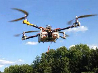
Is the quadcopter supposed to be unstable and I need to correct it continuously? The quadcopter, if flown in stabilize mode, should remain level during hover without stick input. See this video for an example of stationary hover (pitch/roll sticks centered) on a very calm day (flying in wind does require effort and is not recommended for a beginner). Throughout the clip I made no changes to the controls - the onboard controller should let you hover like this with minimal effort.
How much response should I expect? This is dependent on your controller, but generally with the pitch/roll stick pushed as far as it can go the quadcopter should be at about a 40-degree angle to the ground. This means it will be accelerated at almost 0.5g, and should fly forward quickly, remaining stable at this angle but likely dropping in altitude. If pushing the stick all the way forward results in a less impressive angle change, or some sort of oscillation, it is advised to work on tuning. Furthermore, after forward flight, it should be easy to return to stationary hover - as easy as returning the stick to slightly before center to tilt the quadcopter backwards and remove forward momentum (in the process likely gaining altitude) and then returning the stick to center.
Does the throttle need to be continuously adjusted? Generally yes - by small amounts (about 1/10 of stick's range) but continuously for best performance. If in a stationary hover on a calm day, the quadcopter can stay at approximately constant altitude without throttle adjustment. The throttle needs to be adjusted when making any maneuver in this way: when changing from a hover to a moving position (tilted forward/backward) the throttle needs to be increased since less of the motors' thrust is going to counteract gravity (the rest is used to accelerate it forward/backward!). If the throttle is not increased, the quadcopter will lose altitude. When stopping motion by tilting in the opposite direction to motion, such as tilting backwards after flying forward, throttle should be decreased since during the process the forward inertia and backward thrust cancel out but any upward forces are added together. If the throttle is not decreased when stopping/reversing motion, the quadcopter will gain altitude. (example video - after the first maneuver, the quadcopter rises, then throttle is decreased and it is returned to a lower altitude)
What about yaw? Yaw should need minimal adjustment if any. If it is found to require continuous adjustment, ensure your quadcopter is properly balanced with no malfunctioning parts, and the yaw PID tuning parameters have not been changed.
Where do I fly? A big open field is the best idea. Your quadcopter will crash multiple times, so the ground should be soft and there should not be people around (for at least a few hundred feet so you can fly freely). There should not be obstructions such as trees or electrical lines; controlling the quadcopter will be enough of a challenge without additional maneuvering requirements. Prevent people and animals from approaching the quadcopter during takeoff and landing, ensuring everyone (including you) is at least 6 feet away from the model - wind gusts just might carry the quadcopter towards someone's head as it is taking off, and 14-inch blades that this quadcopter is using will cause serious injury. If it is particularly dry or hot, it might be worthwhile to have a bucket of sand or dirt - LiPo batteries do burn hot and possibly explode if drained beyond capacity or punctured during a crash.
How do I land? The best way to start is by practicing takeoff and landing on a calm day with no pitch/roll during flight. First find a throttle level where the quadcopter holds altitude (hover). Then gently decrease the throttle so the quadcopter descends slowly. If you find the quadcopter is getting too high, slowly decrease the throttle beyond the point where it was observed to hover. Be careful though! First, it is very difficult to estimate the speed of an object coming directly towards you from above, and the farther away it is the more difficult this becomes. It is important to trust your transmitter's throttle level marks more than your sense of speed when trying to bring down a quadcopter that has gained altitude (unless you are looking at it from the side), otherwise it is very easy to descend too fast. Descending too fast is bad because the quadcopter has to travel through air that it has already accelerated with its propellers, which induces vibrations and may cause a 'stall' condition in which the aircraft will drop without the possibility of slowing down using its propellers. Poor tuning will show itself most prominently during descents and especially on a windy day. Overall be sure to not fly too high on your first few attempts. I did not go above 30 feet for my first 5 flights.
It is important to keep a flight log. It is linked here for reference, and documents the process of improving PID tuning using multiple methods as well as my learning of piloting skills.
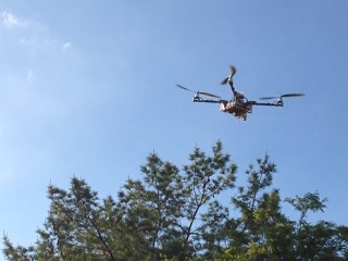
The quadcopter in flight, seen from the ground. The strange shape of propellers is due to their motion being of a similar speed to the camera's recording of each line of the image (top line of image was not captured at same time as bottom line).
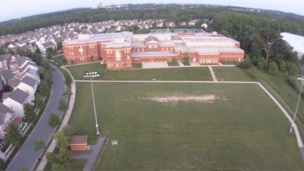
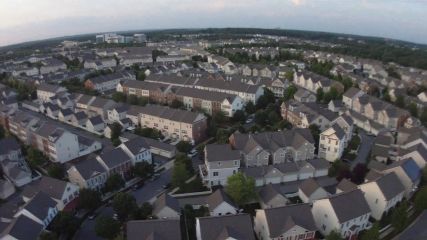
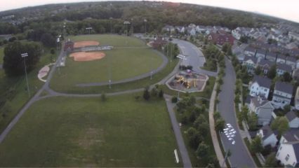
Three views of my neighborhood as captured by the quadcopter's camera.