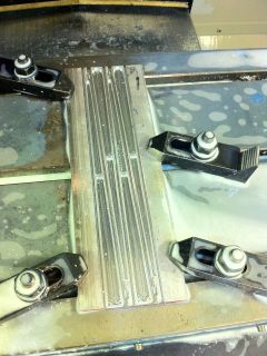
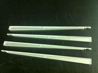
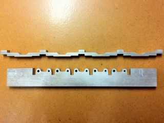
The beams are machined from an aluminum sheet using a CNC mill. The tight clearances are clearly visible on the left. The final product is shown on the right.
The idea for this project came from seeing multiple videos of quadcopters and fpv flying (transmitting live video from the aircraft for virtual flight). After learning some formulas for analyzing beams and structures, some of which came from a statics class, I felt fairly confident that I could build a lightweight frame for a fpv-purpose quadcopter. While the construction involved electrical and control aspects, the mechanical design of the frame was the primary challenge. At the time I was aware of the use of carbon fiber for frame components, but due to the difficulty in machining it and expenses I decided to design an aluminum frame that would be as light as a carbon fiber one (although not necessarily as strong overall).
I used the excellent X-Copter calculator tool to test various combinations of motors, propellers, and batteries (the results were accurate for the configuration I chose; I would recommend this tool as a starting point for a new design). Due to my hopes for long-range fpv flying, a long flight time was necessary. This led to the use of large propellers (14-inch diameter; most quadcopters I have seen use 10 inches or less) since they allow for a lower RPM at the same thrust level and can be better matched to the motor efficiency curve. Additionally this required very large batteries, a total of 12 Ah (or 2x 6000 mAh packs in parallel) at 12V (3S LiPo). The batteries make up most of the weight of this design. At the time of design, the total weight limit was placed at a nominal 2000 grams, since this would correspond to slightly above 50% throttle for hover and would be controllable according to X-Copter calculator.
The frame design began with determination of orientation. Quadcopters can be made in a (+) orientation, where one propeller specifies the forward flight direction, or a (x) orientation where two adjacent propellers are considered the front side of the aircraft. The only real difference between the two is how the quadcopter reacts to the radio control stick inputs (one is 45 degrees rotated compared to the other), however for fpv use it is desirable to place the camera in the space between two propellers (to allow wider angle of view) so for this project the (x) orientation was chosen.
Note that in quadcopters two motors must spin in the clockwise and two in the counterclockwise direction, and this requires two types of propellers as well. Check your controller manual for which propellers it expects to spin which way. To change the direction that a brushless motor spins, switch any two of its three wires connected to the ESC (that is ABC -> BAC or CBA or ACB). Also make sure that all propellers are oriented correctly - matching to the motor direction is easy, then checking that they are not upside down - the edge of the propeller that will hit the air first as it rotates should be angled closer to the ground plane than the trailing edge.
Next the approximate frame weight limit was determined. Based on consideration of existing carbon fiber frames of approximately the same size, as well as the known weight of other components (batteries, motors, etc) the upper weight limit of the frame was set at 150 grams. This is insufficient to choose a proper frame geometry, so other constraints used in the design were 1) vertical deflection at one motor compared to center of frame is less than one degree for a 1000 gram load on that motor, and 2) safety factor (critical stress / maximum stress) of 3 with a 2000 gram vertical load at any one motor with frame center fixed. The former constraint ensures that propellers would be in the same plane for good aircraft controllability, while the latter allows for sufficient tolerance of crashes. While on this topic, if you are designing a quadcopter, you should absolutely expect it to crash and include appropriate protective elements in the frame - otherwise your first flight will not end well.
Taking into account the above requirements, the material chosen for the frame was (rather appropriately) aircraft-grade aluminum, Al-2024. This alloy is significantly stronger than the 'general use' alloy Al-6061, with a matching price increase. It approaches the strength of steel alloys at about a third of the density of steel, and for this reason is used in real aircraft structural parts. The frame would be in an (x) configuration, and for easier construction it was decided that four beams would be made, one for each motor/propeller. The four beams would be bolted together in the center of the frame. Due to the large propeller (14 inch diameter) and required spacing for physical and aerodynamic clearance (in a rather hand-wavy fashion) a beam length of 12 inches was chosen. This would leave a diagonal length of 10 inches for the electronics (batteries, camera, etc).
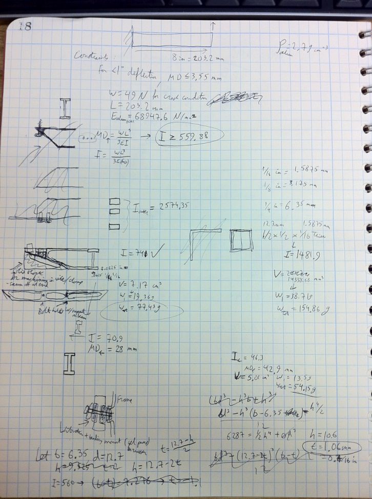
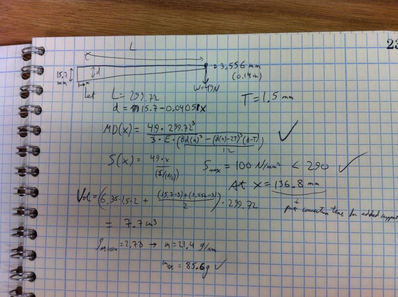
Next the geometry of the beam to match the deflection constraints was chosen to be an I-beam profile, with the assumption that most of the forces on the quadcopter would be in the vertical direction. For those not familiar with beam types, an I-beam looks just like the letter I in its cross-section, and its deflection and stress are highly dependent on load direction. Vertical loads (along the middle line of the I profile) cause little deflection and are the design feature of such a beam; horizontal loads (along either of the edge lines of the I profile) cause significantly more deflection and should be handled only in extreme cases; rotational and torque loads are handled quite poorly. Other common possibilities are round beams with a cross-section like O, square beams, L beams (angle stock). It is also important to note that deflection of a beam has a cubic dependence on beam length, so doubling the beam length will increase deflection by a factor of 8 - thus generally the shortest beam possible should be used. The beam design calculations I made are linked here and here.
The thickness of each element of the I-beam profile was chosen so as to minimize weight while staying within the constraint limits, and also requiring a beam thickness of 0.25 inches as that was a commonly available aluminum thickness for purchasing stock. The overall weight attainable with regular I-beams was over the limit, so the I-beam design was combined with an approximation for a constant-stress beam which allows decreasing weight by changing the cross-section over the length of the beam. This changing of cross-section is done in some real construction projects, although generally it is more economical to fabricate a constant cross-section beam so it is not seen too often. The end result was an I-beam of a constant 0.25 inch thickness with a cross-section varying linearly from 0.5 to 0.125 inches over the length of the 12-inch beam. Four beams would be bolted together in the center.
The motors would be attached directly to the aluminum beams, with additional support pieces due to the relatively small thickness of the beam. The batteries and camera would be attached to a plastic (acrylic) sheet base, which would be bolted to the beams using plastic (high-impact plastic) elements. These supports would both hold the plastic base with all the electronics while in flight, and provide support to the aluminum frame elements when the quadcopter is on the ground/absorb landing impact.
While I designed this much of the frame and made a CAD model, I did not go into detail regarding specific electronics placement and wiring. This proved to cause significant difficulties later on and was one of the major reasons for the subsequent redesign. If you are designing a quadcopter, it is worthwhile to experiment with different electronics layouts and consider wiring requirements, and include this in the CAD model despite how annoying that can be.
Total cost came out to about $800 with the Boscam camera and ArduCopter controller being the most expensive at $100 each, and the two batteries costing $100. Getting rid of the whole FPV package (Boscam/ArduCopter/GPS/OSD/Video transmitter+receiver) will decrease cost significantly, and cheaper options certainly exist for flight controllers. Although after I understood all the features of the ArduCopter unit I was able to adjust flight handling to a much better level than the simpler controllers allow.
Construction of the frame started with machining the beams out of the aluminum sheet. I ordered the sheet from McMaster who boast an impressive 1-inch error margin on a 12-inch long sheet, and the sheet I received was closer to 11 than 12 inches. In a slight redesign of the CAD model, I shortened all the beams to just fit on the stock. Using MasterCAM the profile was laid out, requiring machining from both sides of the stock. I had the idea that all four beams would fit with space to spare on this sheet, but completely forgot about the mill head also needing to fit for proper machining. After some difficult setting up and aligning of the stock, and anxiously watching the CNC mill to ensure the only 1/8-inch endmill in the shop does not break (also using FSWizard to calculate appropriate feed/RPM), the beams were finally complete. They had to be laid out in an extremely compact fashion to fit on the piece, and each toe clamp had to be adjusted. This all was repeated on the other side of the sheet, and the end result was OK although a visible difference existed between the top and bottom halves, which could not be easily explained by alignment issues. I plan to buy much more oversized stock in the future to avoid the difficulties of machining so close to the supports (one might think I learned this lesson with the waterjet but alas).
The beams are machined from an aluminum sheet using a CNC mill. The tight clearances are clearly visible on the left. The final product is shown on the right.
Of course the rest of the sheet was to serve a purpose as well. Both of the sides remaining after that milling operation were cut using a waterjet cutter, to make the additional supports for the motors from one side and the corner sections holding the beams together from the other side. After that waterjet operation, each of those pieces would have to be milled again to create four supports and corner sections respectively with additional tapping required for the corners. Also additional milling operations were to be done on each of the four beams, requiring rather good alignment. That was not a fun weekend.
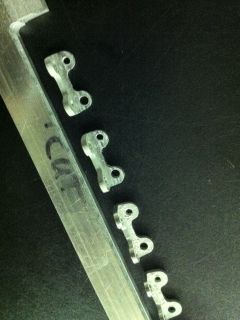
The rest of the sheet is machined into motor supports and corner sections. The corner sections required multiple machining operations as seen on the right.
While on the waterjet, I also cut out all the UHMW plastic parts. This was slightly easier although still rather tight.
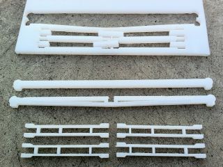
The plastic parts were cut out of the sheet on top using a waterjet cutter.
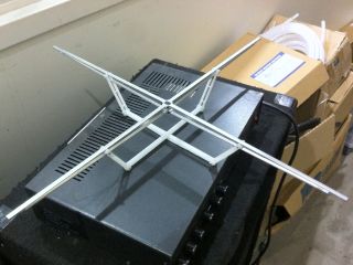
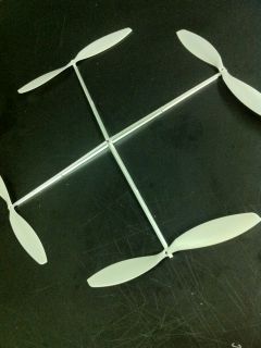
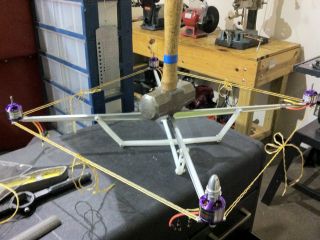
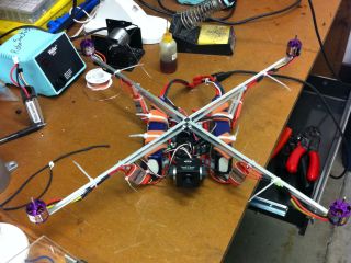
First assembly of the frame using plastic and aluminum parts. On the right, propellers overlaid for scale.
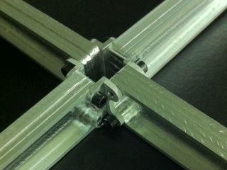
A close-up view of how the four beams are attached to each other in the center using tiny angle brackets.
At this point it was time to assemble and test the frame. The frame itself looked fine, but attaching the motors showed that there was not enough clearance at the bottom to allow them to spin. Fixing that would require an additional milling procedure on each of the four beams; the alignment in the mill was rather approximate for this one and I used an oversized endmill to compensate. Not the best approach but for a difference of 0.01 inches or so I really did not care enough. The motor support pieces that are meant to provide additional holding force to the beam also seemed to have a clearance issue, likely due to the waterjet cut being at an improper distance (for precision waterjet cuts, test the nozzle offset first by making a scrap part). At this point I just milled off the excess until it looked right, so the support pieces bent a bit more than planned when fastened to the motors.

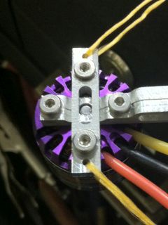
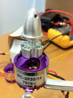
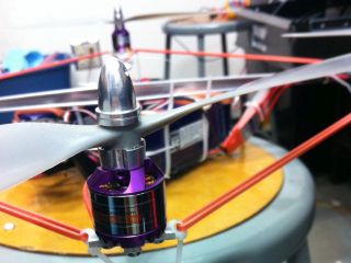
Two different view of how each motor is attached to the end of the aluminum beam with bolts and a motor support piece.
Despite the various slight deviations from the expected construction, the overall frame fit together and stood up well to a few frightening but necessary load tests. Note that rope was added in a square configuration surrounding the four motors, in order to lessen loads perpendicular to the I-beam designed direction (the type that would move two motors towards each other). This was changed to a rubber band between any two adjacent motors in the final stage in order to keep an approximately constant force around the perimeter.
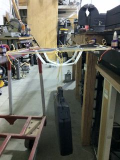
Two load tests were done - on left a tension test using approximately 5 lb briefcase, on right a compression test using approximately 4 lb hammer.
Next the propeller adaptors (of the screw-on type; collar types would seem like the weakest link in the chain here) were drilled using a lathe so they would fit better on the motor shaft. To anyone in a similar situation, I would suggest cutting the motor shaft, since after drilling through the adaptor the thickness of aluminum left to hold on to the propeller and handle the torsion/tension forces from tightening the top was rather small. One of the adaptors broke while untightening a propeller. Furthermore, to take advantage of the drilled hole in the adaptor for alignment purposes requires very tight tolerances. Cutting the motor shaft would not affect stability of the adaptor and would leave a full aluminum threaded shaft on the adaptor to tighten the propeller onto. All bolts used for the motors and the propeller shafts were treated with threadlock to prevent vibrations during flight from loosening important parts. Additionally locknuts (nuts with a rubber pad that prevents slipping) were used for other components.
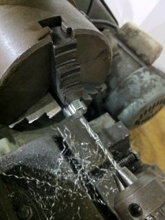
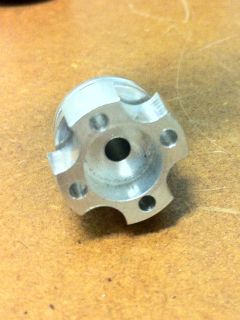
On left, the process of drilling out the propeller adaptor on a lathe to obtain a centered hole. Center and right, two views of the adaptor.
The ArduCopter and transmitter/receiver needed to be set up, and in the process I burned out the USB chip on the expensive ArduPilot controller. The cause was as follows, so you may avoid it: the APM and ESCs were connected to a variable DC power supply (+) and (-) outputs with the output voltage set to zero, my laptop was plugged in to a charger, and I attempted a USB connection between the laptop and the APM. The DC power supply clicked a few times (switching relays) and the APM communication was gone (although lights blinked as before so I believe everything else worked). Likely the (-) output on the DC power supply was at a non-zero voltage to ground, while the laptop (and thus the outside of the USB connector) was grounded through the laptop charger, and somehow this caused a condition the APM was not designed for. Subsequently I bought a new APM and never tested with a power supply to avoid this scenario; plugging in the USB cord while the APM was on battery power presented no problems. Hopefully the previous APM would only need a part replacement but I still have not determined which parts of it failed.
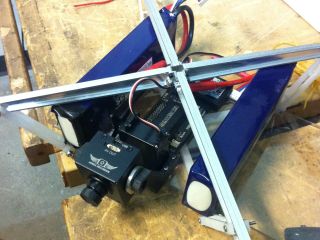
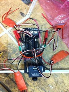
Testing of the electronics layout. The large blue objects are batteries.
It was about time to put everything together when I realized that there was not camera mount or electronics layout plan. After laying out some of the electronics components and marking drill holes with a sharpie, as well as fabricating a camera mount out of scrap plastic, the electronics base was rather cluttered and wobbly. At that point I also realized that none of the wires were in place. Again not a fun time but a necessary lesson in design. Luckily I found some crimp connectors that allowed the use of two large bolts to connect all the positive and negative high-current electronics in a straightforward manner. I even used two different bolt sizes to avoid mixing the positive and negative connections; this should probably be made into a new standard or something. A number of bolts, nuts, and zipties completed the electronics base.
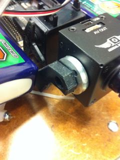
On left, a close view of the improvised camera mount system. Center and right, electronic components and wires are added.
Finally the model was balanced, by adjusting battery locations before tightening the zip ties, so that its center of gravity was directly below the center formed by the beams. This helps to achieve stability during flight, and is similar to what is used in boats (center of gravity below water surface). At this point it weighed in at 1725 grams, well under the 2000 g design limit, and was ready for its first flight.
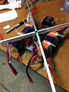
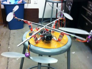
Two views of the finished aluminum frame quadcopter.
After completing the electronics, I waited a few minutes until the sun came up to attempt the first flight. As it turned out, the only good open space close to the machine shop was a large concrete parking lot - to anyone testing an aircraft, it is well advised to do so over a soft grassy area instead. The good news was that the rather unconventional motor/propeller/battery combination worked and was able to lift off at about 50% throttle as calculated. Additionally the frame held together fairly well. The bad news was that flight was extremely wobbly and uncontrollable. Also, after multiple crashes on the concrete a propeller developed a small crack and eventually one of the beams bent, rendering the quadcopter inoperable.
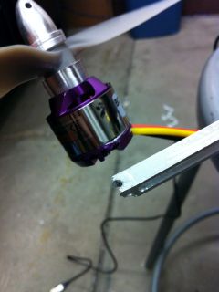
A close view of the broken motor and how it failed at the thinnest part of the beam, as may have been expected.
This project was my most advanced yet, taking about 6 months to complete from the planning stage to the first test flight. There are many ways in which this could have been done better, some of which are listed here.
The initial CAD model should have included the electronic components and some consideration of the wiring. This would allow for a base designed for an appropriate center of gravity and better mounting options than zip ties. Additionally the APM often requires connecting a USB cable to program it, so it should be placed in a way that allows for easy connection. In the current design the APM was placed between two batteries, making programming highly inconvenient.
The camera holder arrangement was poorly planned and ended up being rather inoperable. The servo controlling camera angle was not well attached to the base.
The APM and camera mount should be attached with vibration-reducing structures for better picture quality and better gyro/accelerometer outputs for stability.
The frame should be more rigid, especially taking into account forces in directions other than vertical. This particular frame was quite susceptible to forces that tend to twist the frame, and the central angle brackets and outside rubber band supports were insufficient to maintain rigidity during regular flight conditions. It should be noted that motors exert torsional forces during acceleration/deceleration and can be expected to exert other forces and torques due to aerodynamic effects.
The weight-saving measures on the plastic parts were unnecessary, as the weight reduction was almost negligible and material strength is important in these elements. Having the plastic supports angled in this frame design also caused them to bend due to creep strain, and the angle did not serve any significant purpose. The weight savings on the aluminum could have been decreased to be closer to the design limit weight.
More time should have been taken on machining difficult parts. But a much better alternative would be to design parts that do not require complex machining and still retain the necessary features. Partially I wanted to mess around with the CNC mill and waterjet, and see whether the statics formulas actually worked for a changing cross-section beam. While I had the chance to do all that, if I had to do it over I probably would rather design a simple part that could be machined with very few operations and not requiring much precision. Knowing how much of a tradeoff to make between fully optimized parts and essentially stock items was an important lesson here.
Regarding statics, while the beam was pretty and could not be bent by hand in the vertical direction, it could be bent by hand in the perpendicular direction. Additionally, the beam's weakest point was at the attachment of the motor, where the cross section decreased suddenly and a bolt hole/countersink additionally decreased the amount of metal. While this was only realized after the fact, this point is unsurprisingly where the motor broke off after a crash. The lesson is to not maintain mathematical analysis results as accurate after changes to the design cause it to deviate from the initial model. In this case the mathematical analysis was for a linearly changing cross section without bolt holes, while in the real case the cross section changed abruptly at the end of the beam and bolt holes were present for holding the motors.
Landing gear is another important consideration. In this model the landing gear was at the bottom of the electronics base, and while sufficient for controlled landings and takeoffs, did not provide adequate protection for crash landings. Some designs use soft landing gear protrusions attached directly under the motors, which allows for a softer landing at large angles from the ground plane. Having the landing gear inside the perimeter of the motors decreases the angle at which the aircraft will land properly.
The propellers would often become loose in the propeller adaptors, spinning freely even though the adaptor was attached quite tightly. This was made worse by the fact that adaptors are generally sold as clockwise-tightening only, while the best arrangement for a quadcopter would be to have two clockwise and two counter-clockwise tightening. Some ideas for better propeller attachment are presented in the carbon fiber model.
The quadcopter and APM should have been tuned for proper flight control before doing an actual flight. I did not appreciate the importance of this step until after I was effectively unable to control anything during the few test flights this quadcopter undertook. This step can be done by holding the quadcopter in one's hand for small models, and for large ones such as this it could be done by setting up a testing rig where the model is held with ropes in a way that allows it to rotate freely but not move laterally. Tuning is also necessary with other controllers - the less expensive varieties do not need a computer connection to do this but also generally have less parameters to adjust than the APM (which has at least four variables for each axis). The carbon fiber model describes tuning in more detail.