96-LED Music Visualizer and Interactive Light
February 4, 2013
Idea
The concept for this project came about due to the need to visualize music using something like a color organ. After getting a 48-channel LED controller kit, and testing it with 16 RGB LEDs (each LED taking up 3 channels so each color is independently controlled) I was happy with the visualization results but the resulting light output was barely visible, and I wanted something to light up the whole room. I kept the same controller and bought a pack of 100 RGB LEDs, of which I used 96 to connect 6 in parallel to each channel. The resulting light output is approximately 6 times that of the original visualizer, and the LED strip takes up an impressive 8 feet. It lights up the room and ceiling very nicely.
Supplies
- Pack of 100 RGB LEDs (only 96 are used here)
- Set of 300 resistors for the LEDs (for 5v: red gets 160+ Ohm, green and blue get 100+ Ohm)
- 16 transistors for each LED group (choose NPN or PNP based on your controller (sink or source) and make sure to consider whether you want common emitter or common collector as this will affect whether you need common anode or common cathode LEDs)
- Lots of wire, based on the geometry of your setup - I used thin speaker wire from radioshack as it was cheap and flexible and the linear setup took 75 feet (note the controller was placed in the middle to save wire length)
- 48 channel LED driver and USB cord
- Filter capacitor for the LED driver (250VDC, 380uF)
- 5V 6A power supply (20mA per color per LED gives 5.76A, and controller will draw some current)
- Wood panels to use as LED strip
Construction
The project requires running 6 RGB LEDs in parallel since there are effectively 16 RGB channels and 16*6=96 is as close to 100 as possible. Thus 6 LEDs will be in a group that shows the same color but the group will of course be much brighter than a single LED. In order to run multiple RGB LEDs they need to be wired in parallel, since if they have a common cathode or anode they cannot be wired in series and still have each color independently controlled. When wiring the LEDs in parallel, make sure that the input for each color has its own resistor on each LED - if you have one resistor for multiple LEDs in parallel, or a resistor on the common lead, something will get fried. Then the resistors are wired in parallel to the power supply along with the common lead which does not need a resistor.
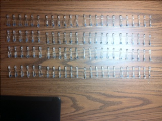
Being excited about the project I set off soldering the LEDs into groups of 6. 672 solder joints later here is the finished result:
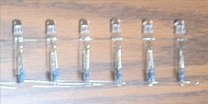
 Here is a single group of 6 LEDs and on the right all 16 of them. Note how the resistors and common anode are wired in parallel.
The LEDs worked well in parallel, and could be connected directly to 5V since the resistors limited current. I went on and even connected wires to 8 of the LED groups but then I was stuck in a very unfortunate situation.
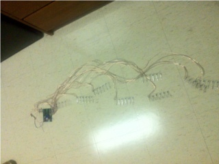 Half of the project completed.. but it looks like crap!
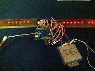
The wires got all tangled up and the solder joints were coming apart due to stresses on the frail structure, but even worse than that the controller wouldn't work. After a lot of trial and error I ended up testing the controller using an oscilloscope where I witnessed just how noisy the TLC5940s were at doing the PWM control. They were in fact noisy enough to cause the microprocessor to reset due to voltage surges which made the controller unusable. I added a large capacitor to the power input to the controller, and wired very close to the controller for most effect at high frequency, and that enabled the controller to function properly even while doing PWM on a relatively high current load. But I still had to fix the mess that resulted from the tangled LEDs.
It took me an unfortunately long time to realize that the LED arrangement really needed an external structure to hold it together, however once I found an old wooden shelf the execution of the concept was fairly straightforward. Somehow combining a stained wood structure with high tech electronics seemed like it would be really neat visually (although the staining was just a fake layer). I cut one of the boards from the shelf into thin strips, each about 4 feet long, and drilled holes for the LEDs. The holes are spaced approximately 0.9 inches between LEDs and twice that between groups of LEDs so that the difference between groups is more obvious.
Next I milled out the inside of each of the strips from one side to fit the LEDs, transistors, and wires inside, leaving about 0.25 inches on the bottom so that the tip of the LED can stick out and most of the light is emitted outwards rather than into the wood structure (note LEDs can emit light at weird angles from the tip so having it entirely surrounded may reduce apparent brightness).
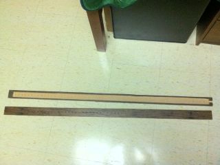
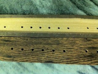 On the left is a photo of the two LED strips, on top is the milled-out back, and on bottom is what it looks like from the front. On the right, a close view of the LED strips showing drilled holes for a group of 6 LEDs.
Then came the fun part of undoing my hard soldering work and redoing the 672 solder joints so that the LEDs could fit in the milled out space properly. The only reason I finished that was because my other alternative was studying for finals. Next the transistors were added since the LED controller had difficulty outputting full current to each channel, so with transistors the controller would output at most 1mA and the LEDs would still get all the current they need since they have their own resistors. Finally the wires were added in and the LED strips were complete. There are 13 2-conductor cables going into each LED strip, 12 of them low current connectors to the LED controller and one for the high current plus and minus supply.
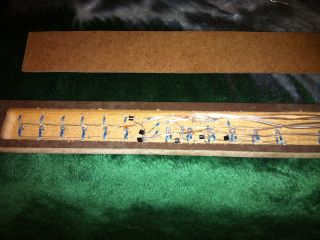
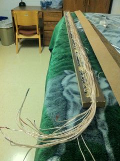
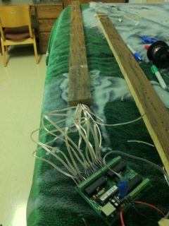 On the left, a close-up of two LED groups from the back, note the transistors, resistors, and wires connected. On the right, a photo of all the control wires installed in the back of the light fixture, and then connected to the LED controller. Each wire was labeled with a sharpie color pattern to keep track.
Once the second LED strip was completed, it was time to test the controller. With the capacitor connected, it worked on the first try! However there were weak spots in some of the solder joints so I needed to go back and redo those subsequently.
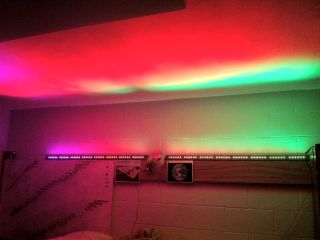 First test was successful. Next both LED strips were installed on the wall of my room and were found to be bright enough to light up the room, as expected.
Results
Once everything was working properly (and it took a few soldering re-dos to fix), a few weeks were spent optimizing the software algorithms used for music visualization, and during that time I also added features such as strobe light and manual control to the software. As the LEDs are bright enough to light up the whole room, strobe light mode is actually pretty cool, and being able to change the color of the lighting (or set up a pattern for it) is great. The projections of the LEDs on the ceiling though, as you can see in the last photo above, really make this light stand out.