The 96-LED music visualizer amazingly survived over 3 years and 3 moves, despite the mess of wires and soldering inside the wooden structure. However, now that I had moved off campus I had access to a bigger room and the LEDs did not seem as bright in the bigger space. Additionally, another bad solder joint showed up in that circuit, so I decided to upgrade to the industrial manufactured individually addressable LED strips along with a faster controller. The original version of the visualizer had ~10 LEDs, the next one ~100, so it is only fitting for this one to have ~1000 (and stay tuned for the next update!). In my room I could fit a 5 meter LED strip, and based on the timing requirements about 300 RGB 'pixels' could be used for visualization. Thus this visualizer consists of 4 parallel 300-LED light strips for 300 pixels spread over 1200 LEDs for increased brightness.
There are three main requirements to consider: brightness, power, and timing.
Brightness can be evaluated quantitatively, but the units involved are not intuitive to me so I just settled on around 1000 LEDs to give a 10 times higer light output than before.
Power requirements are directly related to brightness (and here I have already assumed a 5V LED strip): for typical LED strips each LED will draw 61mA at full power (20mA per color and 1mA for the logic circuit). Then the total current for 300 LEDs is .061*300=18.3A. Based on my budget I could go with a 80A power supply, giving 80/18.3=4.37 or 4 LED strips of 300 LEDs each. The associated power is 4*18.3A*5V=366W when all LEDs are on.
Timing requirements dictate how many LEDs can be in series (how much data they display at once) as well as how often your software can send new data/how smooth animations will appear. The LEDs in a single strip are wired in a daisy-chain fashion so the data for each LED must be written sequentially. In principle the LED strips can be chained together to be very long, but this will reduce the maximum update rate achievable. The FastLED library communicates with the LEDs at 800kHz (which is also the fastest rate the WS2812B supports), and with 24bits of data per LED this means 0.03 ms per LED to transmit data. With 300 LEDs the time to update them is 300*.03ms=9 ms. The maximum update rate is 1000/9ms=111 Hz. However this does not take into account any delays due to microcontroller processing the data (it cannot receive and transmit, or process and transmit, at the same time). So for outputting data received by serial communication we would expect a maximum of perhaps half of that, or 55 Hz (about the same as a typical TV screen/monitor refresh rate (but those put out ~4000 times more data with each update)). This rate is inversely proportional to the number of LED strips in series. Thus it could be possible to connect the 4 LED strips all in one chain, but then the update rate will drop to 55Hz/4=13 Hz. To give myself plenty of overhead (for possible processing on-chip) I connected the 4 LED strips in parallel, thus each displays the same data but all four can be updated at the same speed as one.
Compared to the previous hand-soldered version, the effort here is negligible. All I needed to do was unroll the LED strip and attach it to the ceiling, then solder all the wires together. Luckily there is a pipe running across the ceiling, so I attached the LEDs to that. The LED strips even have an adhesive backing so this could have been an almost zero effort project, but I did not want the LEDs to be permanently attached to this pipe so I instead wrapped them onto the pipe. It's possible to use string for this but I had some extra floss so...
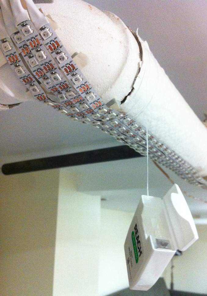
Floss is used to attach the LEDs to a pipe. This actually turned out surprisingly well, the floss was in a nice package that made it easy to wrap around the pipe, it was strong, and it gave off a fresh minty scent.
Next I soldered the wires together. For the power, there would be 4 wires (1 to each of the LED strips) plus 1 wire to the power supply at each end, so one would need to solder 5 wires together. This sounds annoying but there is a little trick to make it easy. Find a wire with thin strands, cut a section about 2-3 inches long, and strip off most of the insulation - you will have a little bundle of strands.
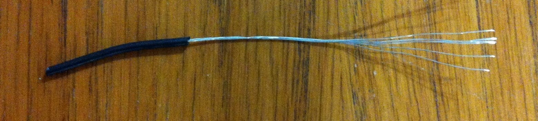
Wire strands illustration.
Then pull out a single strand, and wrap it around all the wires to be soldered together. Start with the 4 to the LEDs, then add in the other wire and continue wrapping. If successful, the wire wrap will hold everything in place, allowing you to work with the soldering iron at your leisure. The strands will accept solder well, so the whole joint can be soldered securely.
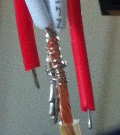
Wrapping wires together before soldering.
Then solder together the 4 control wires and make the connections to the Teensy LC (pin 17, which is the only 5V output on the LC). Also connect the +5V and GND connections of the LED strips to the Teensy LC.
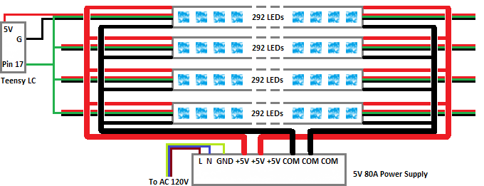
The wire connections required for this project. Thicker lines represent bigger wires that can carry more current. There are 5 wires at either end of each LED strip, two (+5V, red and 0V, white) are connected directly to the power supply while the other 3 are connected to the Teensy LC (DATA, green and +5V, red and 0V, white). The white wires are drawn as black on the diagram for clarity.
Finally (after initial programming and verifying the Teensy works) cut the USB power trace on the underside of the Teensy (this looks like a pad split in two - cut between the two halves) so that it is powered only by the LED's 5V supply and not by the USB (since this will try to use USB to provide power to the LED strips and possibly mess up your computer).
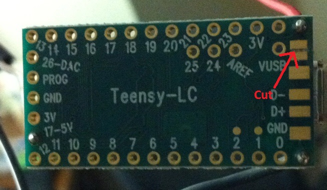
Location of the trace to cut in order to disconnect Teensy LC +5V from USB power.
Ultimately the goal is to have the computer do all the 'heavy' processing, and have a microcontroller that acts as an interface between the computer and the LED strip, writing out data as fast as it comes in. But first we need to establish that the LED strip and power supply are working properly, and that the microcontroller is fast enough for the job (this will determine what update rate is used in the computer software).
When power is applied to the LED strip, without a control signal it sits idle with the LEDs powered off (but still drawing ~1mA per 3-color LED for the logic circuit). To check whether the strip is working properly, I wrote a script that turns on just 1 LED at a time (Moving LED Test), thus allowing for testing without a massive power supply (you could probably power a whole 300-LED strip off USB just for this test, if you did not have any power supply available). The next script (Bar Test) lights up the entire strip incrementally, to test the power supply capacity. Both scripts can be used to determine how fast your microcontroller can update the LEDs.
This is targeted towards the Teensy LC (which I think is an ideal controller for this application), but it should also work with arduino-like boards. First install Arduino if you haven't already. Next install Teensyduino (which expects an existing Arduino installation). That should be it for installations!
Open Arduino, and under "Tools->Board" select the Teensy LC, "Tools->USB Type" is Serial, and "Tools->CPU Speed" is 48 MHz.
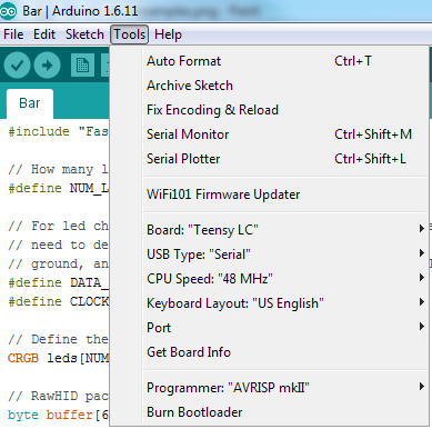
This is what the Arduino Tools menu looks like with the above settings.
Note that initially I intended for this to be a RAW_HID device to avoid COM drivers and hopefully speed up communication, however this ended up being much slower than sending data as a serial device! There is a more detailed explanation about this at pjrc, where one notes in the "Operating System Differences" section that Windows performs worst with small packet sizes. For RAW_HID packets are limited to 64 bytes (and at best 64 bytes per 1ms), whereas for serial communication the packets can be large (I use a whole 900-byte packet to carry all the information for 300 LEDs, which speeds up communication considerably). The maximum common baud rate of 115200 may seem to be a limitation for the serial device, however the USB serial communication with the Teensy takes place at 12 Mbit/sec regardless of the baud rate setting in the script (as outlined here). Thus all you have to do is select Serial for USB Type to get the communication fast enough to be usable here (update rate tested up to 20 Hz with 300 LEDs, with >50 Hz likely attainable).
The communication with the LED strip is done by the FastLED library, which comes with Teensyduino. If you already have an idea of how to program the Teensy, you can use one of the included examples as a starting point. The examples are found in Arduino under "File->Examples->[Examples from Teensyduino Libraries] FastLED". For the Teensy LC the DATA_PIN is 17, and there is no need for a CLOCK_PIN with the WS2812B LED strip (I left the default definition of '13' in the code).
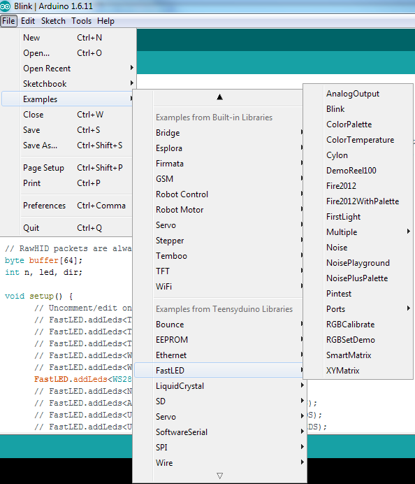
Where to find the FastLED examples.
This test lights up one LED at a time, and this LED 'bounces' back and forth on the LED strip (this makes it easier to confirm that the right number of LEDs is set and the communication speed is OK). It is based on the 'Blink' example, and is set up for the 300 LED strip. The ino file can be downloaded here.
In testing with the 300 LED strip, the power draw for the teensy+LED strip was 0.32A at 5V (=1.6 W), which makes this test great for testing the hardware without a big power supply. The Teensy LC itself running the script takes 0.01A (0.05W), and the dark LED strip takes 0.27A (1.35W) as already mentioned.
The test includes a 10ms delay between each LED strip update. By timing how long it takes for an LED to move across the 300 LED strip a few times, I found that the updates occur every ~18.7ms (53 Hz), meaning ~8.7ms is the time to write 300 LEDs, or 0.029ms/LED (24 bits) or 827.6 kHz comm rate (assuming negligible time for other script instructions, since it runs at 48MHz).
This test lights up the entire LED strip one by one, and then turns off the LEDs one by one. Its main purpose is to test the capacity of the power supply, since in the middle of each period the strip is drawing its maximum rated current. It also shows whether any other connections and wires along the way are sufficient to supply this current. The ino file can be downloaded here.
For the 300 LED strip, connecting the power supply at only one end of the strip results in 'yellowing'/yellow tint of the far end LEDs, because of a voltage drop by the earlier LEDs. You can see the far LEDs become whiter as the earlier LEDs turn off thus not drawing current anymore. To resolve this, you will need to connect a source of power at the far end (this can be done with high current wires running from the original power supply alongside the LED strip). This is the suggested setup in the wiring diagram above.
An illustration of the LED strip having a yellow tint when not connected to power at both ends.
This script is the 'final' version that will get serial data and write it out to the LEDs. Like the earlier LED controller, it has an animation section that plays before USB is connected. In this case I was lazy so the animation is simply the earlier bar test.
This will show up on the PC as a COM port, and will receive 901 bytes triggering an LED strip update as soon as the data comes in (the first byte can transmit commands, which is not implemented yet as I haven't found a need for any commands). The Teensy LC will expect serial data in the format [Command byte] [LED1 Green byte (1G)] [LED1 Red byte (1R)] [LED1 Blue byte (1B)] [2G] [2R] [2B] ... [300G] [300R] [300B]. As soon as it receives the last byte it will write out the data. On the PC side, the software should write out the whole 901 bytes at once (into an appropriate buffer) so that the data is transmitted as quickly as possible. If there is a >20ms delay in the middle of the 901 byte packet the Teensy will ignore the whole packet and start over with the next received byte. This serves as a mechanism to synchronize the Teensy when for instance the PC side software is restarted.
I tested this with an update rate of 20 Hz set by the PC software (transmitting 901 bytes every 50ms), which showed a fairly smooth motion that implies no missed packets and generally uniform timing. Bringing the PC software window into focus (as the 'active' window) seemed to improve the timing. Faster update rates are very likely to be possible.
I was hopeful that for this project I would be able to reuse most of the code from my earlier Lightshow software. For the most part this was true, the only change was in the visualizer algorithm. With 300 LEDs instead of 16 with the previous version, I saw embarrasing flaws in my processing of the FFT data which, when fixed, resulted in a very nice display. The issue stemmed from the Windows native audio device defining a buffer size in bytes whereas my program defined it in shorts thus having half a buffer of random data. This didn't have much of an effect on the 16 LED version because of the reduced resolution, but it is still possible to see some artifacts of this as 'noise' when there is no sound playing in the videos of the previous device.
I did a brightness comparison with the previous version by taking a photo of both at full power in the same location and with the same shutter speed/aperture. The new one is definitely a lot brighter! Unfortunately I am not quite getting the full power output, as about half of the power is dissipated in my "high-current" wires! The voltage at the power supply is 5V and at the LED strip (when all LEDs are on) only 3.2V, with the difference being dissipated as heat in the wires between the power supply and LED strip. Getting thicker wires should improve the brightness even further!
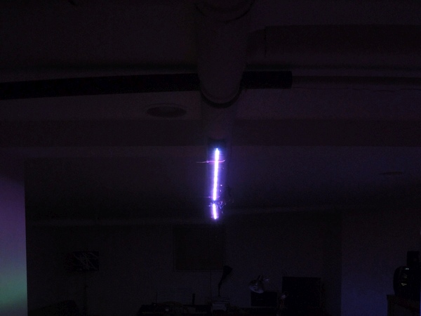
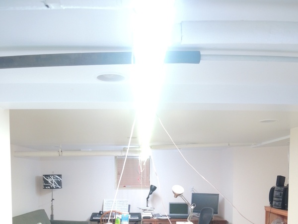
A 'before' and 'after' comparison of the 96 and 1200 LED visualizers using the same camera settings.
Also to get a better idea of how it compares to the previous version, I ran a visualization with the same song as in the previous video (The Algorithm - Trojans), which can be seen here.
Another song that shows off the FFT algorithm working as intended is (Vector Lovers - Girl and Robot) and the video of that visualization can be seen here.
Overall I am quite happy with the result! Hardware-wise this was quite easy (definitely better than soldering everything by hand) and if you copy the code above there is almost no programming required. A replica could be done for under $200, and if you don't need that many LEDs the price drops quickly to under $100.