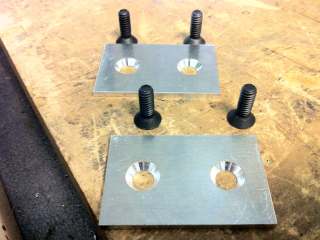
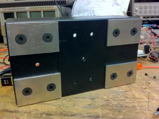
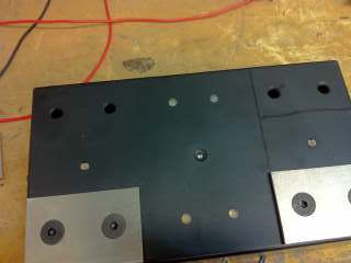
An aluminum sheet is cut into four rectangular plates, and each of those is drilled for attaching with two bolts to the plastic box. The images above show individual aluminum plates as well as how they attach to the plastic box.
The original Lightning Reaction (a reaction game that shocks the losing player) having become an established classic, I realized what a shame it was that the device was so shabbily put together. The case was an old computer power supply with some holes cut in it for the LEDs and two controllers. The controllers were two random wood blocks with aluminum attached by rubber bands, and some buttons glued on. While it is a good example of the 'hacked together' appearance of my earlier projects, I knew that this design had outlived its time and tore it apart a few months ago. As it turned out though, the underlying idea would not get out of my head and now it lives on as a much prettier and more elegant manifestation.
An important consideration in the design of the new Lightning Reaction was its shape factor - the old one was three components (the game itself and two controllers) connected by multiple wires, and was not pretty to carry around. The new design would have to be portable and robust (ie can be dropped, turned upside down, stowed in a backpack). After considering multiple approaches with metallic contacts integrated into the device itself, I came to the conclusion that the traditional pushbutton that was used in the original game would have to go. Securing a pushbutton would require complicated machining of pieces that fit together to a close tolerance for the final product to look any good. A clear alternative to pushbuttons would be a conductive touch sensor, similar to the one used in the original Lightning Reaction. However the conductive sensor in the original game served as a signal to start the countdown timer while here it would serve to end it. Therefore another sensor is needed to start the timer, and that would be a proximity sensor (implemented with a photodiode/comparator circuit). Additionally this change meant that a single conduction (touch) test through both controllers would be inadequate, and the test would need to be performed independently on each controller.
All of these extra sensors complicated the design electrically, but that was no challenge at all compared to the original project since I knew practically nothing about circuit theory back then. Now the challenge lied mostly in making everything look pretty and ensuring the wiring would not fail due to mechanical reasons. Again considering the robustness of the final product, I chose to buy a plastic case specifically for this project, which I proceeded to modify. This kept the underlying mechanical framework quite sturdy and resulted in a much more polished final product.
As a broad overview, Lightning Reaction Redux is a reaction game for two players. Each player controls one half of the Lightning Reaction game container (hereafter 'box'), with each half containing two metal plates. To start the game, both players place one hand over their side of the box. The proximity sensors register the presence of both players and then a random countdown begins. When the countdown ends, a bright red light turns on in the middle of the box, and the first player to touch both of the metal plates on his/her side wins the round. The second player - you guessed it - receives a shock for losing. Of course to be fair, if a player touches the metal plates before the light turns red the countdown starts over, and if a player removes his/her hand the proximity sensor causes the game to stop.
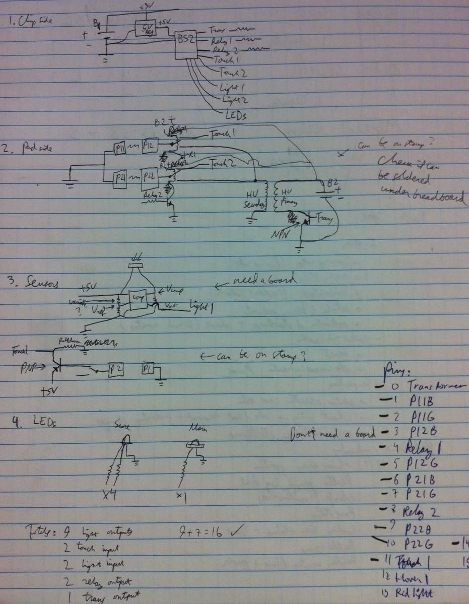
Since this was intended as a relatively quick project, I don't have fancy computer generated diagrams. The basics are still conveyed well enough by this operational overview chart.
The first steps of the project were strictly focused on the outside appearance. The metal plates were machined first, and then holes drilled in the plastic box for the metal plates, 5 LEDs, and two proximity sensors. The drilling is fairly straightforward once you have all the necessary dimensions; the only tough part is countersinking the metal plates which is best done with a drill press.
An aluminum sheet is cut into four rectangular plates, and each of those is drilled for attaching with two bolts to the plastic box. The images above show individual aluminum plates as well as how they attach to the plastic box.
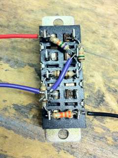
Next, the backbone of the electrical system, the power circuit, is put together. This circuit includes connections for two 9V batteries and the power switch, and provides power to all components that will be added in subsequently. The 18V circuit is connected directly to the transformer and two relays, both of which can be seen in the photo, while the 9V circuit supplies power to the basic stamp exclusively. The ground is common on all components (and is the negative terminal of the main 9V battery) and one metal plate on each player's side is grounded as well. This allows for the shock to occur going from transformer to ground, while touch detection is from a transistor to ground. The two relays independently isolate the transistors on either player's side when the transformer is powered up so the low-voltage touch sensors are not damaged by the high voltage from the transformer during a shock. Note that in this project to maintain a quality look the switches are much better integrated than in any of my previous projects, with properly sized bolts for the selector switch and a tight-fit opening for the power switch.
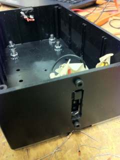
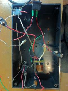
The two switches and the power circuit in place. Visible items are the power switch, 9V battery connectors, high voltage transformer, and two relays. Additionally note that all connections are soldered and have shrink wrap on them to ensure robust electrical connections. The circuit is not secured inside yet since other components will need to be under the wires shown.
At this point it is necessary to build the game so all the outward facing components are in place first and can be covered by other components as the build progresses. This means all the LEDs and proximity sensors need to be wired next. The LEDs are fairly straightforward (a worthwhile point being that each individual color on each LED requires its own resistor, rather than a common resistor for multiple LEDs, in order to avoid either burning out LEDs or having unpredictable brightness). The proximity sensors were based on a photoresistor, which is a device that changes its resistance based on the amount of (visible spectrum) light incident on it. If a player holds his hand over the photoresistor, the hand will block out any light coming from above the device, and thus an increased resistance will be measured. If the player moves his hand away the photoresistor will be exposed to the light again and its resistance will decrease. Of course this setup requires light, and furthermore light from above the game box. Subsequent testing outside on a cloudy day showed that this method is far from ideal for unexpected lighting conditions, although it works reliably inside. Another alternative would be to use an infrared proximity sensor, which sends out an infrared light signal and checks how much of the signal is received, thus requiring no outside light for operation. However the distance range I was looking for would necessitate purchasing a $10 or so infrared sensor, which I thought would not be worth it if the task can be accomplished well enough by the photodiode which I had readily available.
In order to turn the change in resistance of a photodiode into a useful signal (for the basic stamp a binary true/false signal would work best) an op-amp was used, wired in a comparator configuration. This means that the photoresistor is connected to both ground and a positive voltage (in this case +5V) and the voltage read by the op-amp is somewhere between 0 and 5V based on the resistance of the photoresistor. Two regular resistors (again between ground and +5V) are used on the second input of the op-amp to provide a constant reference voltage. If the voltage on the photoresistor side is lower than the reference voltage (implying higher resistance, or darker surroundings) the op amp outputs a binary true signal (>3V) to the basic stamp, which the stamp interprets as "a player has placed his hand over the sensor". Otherwise (lower photodiode resistance, so it is exposed to light) the op amp outputs a binary false (<2V). One photoresistor and op-amp comparator circuit was built for each player side, and all the LEDs were wired.

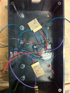
The proximity sensor circuit is soldered together (left), and then the sensors and LED lights are glued in the box (with proper spacers and tight fit, so the glue works effectively) (middle). Finally, a view from the outside so far (right).
Now that the visual presentation part's done, it's time to put in the fun electronic components. After placing protective tape over the LEDs and proximity sensors, the power circuit from above is secured inside the box.
The power circuit from above is inserted in the box above the LEDs and proximity sensors, this time to stay for a while.
Due to the uncertainties associated with using a photoresistor for proximity measurements, the selection switch that was previously used to select shock intensity was converted to adjust the sensitivity (ie reference voltage to the op-amp) of both proximity sensors. As a consequence the shock intensity is the same for all games.
The switch is connected to both ground and +5V, and outputs multiple voltage values in between those two. Outputting a higher voltage means that the photoresistor output is more likely to be less than the switch, which would be registered as a true by the op-amp. Thus the switch allows for a manual adjustment when, for instance, playing in the dark or in bright daylight.
While this is far from the ideal way to approach the proximity sensing problem (and the resistors on the switch are to some extent arbitrary), I didn't want to spend any more money or time on getting a perfectly working solution
This switch is used to select a reference voltage for both of the proximity op-amp comparators. Sliding the switch changes the point in the resistor chain from which the voltage is sent to the op-amp.
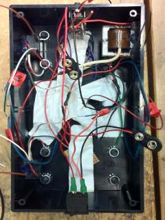
Now that the supporting hardware and electronics are in place, the brain of the system (the very same BS2 from the original Lightning Reaction) can be placed in the box as well. Unfortunately the stamp will require at least one connection to each component already installed - I overcame this problem by using extraordinarily long wires for each component, which was great for connecting the basic stamp in this final step but had the drawback of filling the entire box with a mess of wires when it was time to put everything together. After all the basic stamp connections have been tested, the basic stamp controller is programmed using only one 9V battery. This disables the higher-voltage transformer and relay circuits in case the previous program messes something up. With the correct program loaded, and pin numbers double checked, the second 9V battery is placed in to complete the game internals.
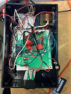
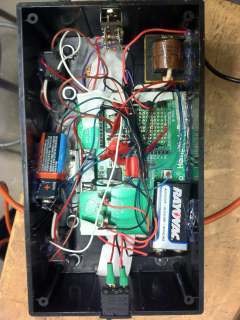
The basic stamp board is placed inside the box and all necessary wires are soldered in place. Finally, the batteries are added and programming/testing can begin.
The program of the original Lightning Reaction was used as a basis for this code, but since additional sensors and indicator lights were added a lot of the code needed to be changed as well. I took this opportunity to make those parts of the code cleaner and faster (ie less PAUSE statements) for a more dynamic game. As a result many unused variables got thrown out and the code overall is more straightforward. Other than that, the code itself is in BASIC and has comments so I won't go into detail here. The code file is available for download: lightning_reaction_redux.bs2.
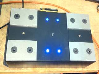
The completed game, in waiting mode with all 4 blue indications lights turned on
The final product turned out to be as I expected - the case was sturdy, the internal components were well attached mechanically and well connected electrically (no unsoldered/uninsulated connections), and all the sensors worked as expected. It was very exciting after the long hours of work to see the sensors come to life, and rewarding to test the combination proximity/touch sensors which turned out very fast and responsive (proximity only in the right conditions though, ie overhead light). The programming was also improved a lot for this game, removing a lot of the waiting time from the previous code as well as removing redundant code bits, while also adding fairer rules since the touch and proximity detectors are independent for each player and can be used to keep a more accurate score. In terms of player feedback, the indicator light use was improved to output status (which player has the proximity sensor recognized, how many points each player has, and whether a tie occurred). Additionally, now each player could score points simultaneously and a new rule was added causing players to lose points if they quit the game after the countdown has started (possible due to the independent proximity sensors). As it turned out during subsequent testing, the actual countdown delay seemed too long - maximum time is estimated at around 15 seconds, but in a tense setting such as that created by the countdown this is quite long. So a shorter time will be considered solely to keep the game moving at a faster pace. However a flaw in the rules was found in that a player continuously tapping the metal plates, while losing all his/her points, would effectively never get shocked. This has prompted a change of rules so that if a player attempts this, the other player would gain points and soon win the game.
A wonderful feature of the Redux design is that all of the hardware components (touch/proximity sensors, shock, lights) can be controlled individually by the microchip (basic stamp). This makes for a very powerful platform allowing for multiple variations and game types. Some recent suggestions were: 1) if a player touches the plates before the red light is on, that player receives a shock; 2) both players receive a shock and whoever lets go first loses. Both of these variations could be implemented entirely through some software modifications, and probably will be added in the future. Additionally, non-shocking versions and even non-reaction based games can be implemented, although that seems to detract from the original purpose of the game. Overall I am quite pleased with how this turned out, electrically and mechanically, although the internal wiring was a lot messier than I originally imagined. But it's not like I'm putting those photos online right?