LED Strobe 2
October 18, 2011
See original version (September 15, 2011; circuit embedded in flashlight handle) here
Need
The need to create a second version arose from an unfortunate accident (read: dropped by a careless person (not me)) that rendered the first one inoperable. Of course since the design was integrated into a flashlight handle, it was impossible to fix the problem without literally ripping the whole thing apart, which was strange because in one sense I could let out my anger by breaking the various enclosings but at the same time this was my own creation I was dismantling.. It turned out that due to its solderless breadboard the first design was prone to losing connections (especially when dropped), and that is why I chose to use a soldered perforated board for this project. The circuit is exactly the same, except one diode is missing (the one supposed to be connected to the base of the transistor). Turns out it is not necessary, and while it's not the best for the transistor this is a viable option if you don't have a diode handy (I just completely messed up the soldering with a dirty iron so I didn't bother to put the diode in series, and the strobe worked just as well).
Also, since this was a chance to remake the whole thing, I took adequate photos of all the internals so you get an idea of what the project entails. I even drew a quick schematic, also shown below.
Supplies
Same as for the original version (link in header). Instead of a solderless breadboard use a perforated board with some copper already on it, they sell those at RadioShack. This will be used for soldering all your components.
Construction
Same as for original version, just follow the schematics.
Photos
All said and done, I finished the circuit despite the frustration of soldering a PCB with a dirty iron, and it worked just the same as the last one. Hopefully it will turn out to be a bit sturdier. Here are the photos:
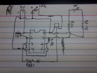
My hand-drawn schematic of the strobe circuit. I haven't had a whole lot of practice drawing these so it may not conform to some standards, but it gets the point across. For a computerized drawing (by another author) see link in original project description. Note the resistor names are color coded: RBR=red black red (gold), YVB=yellow violet black (gold), BrBR=brown black red (gold), BrBB=brown black black (gold). They are this way because I was drawing the schematic based on the physical setup of the original circuit.
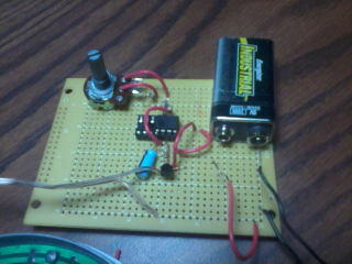

Side views of the circuit board from left and right. The 9v battery, speed control potentiometer, transistor, and 555 timer are clearly visible.
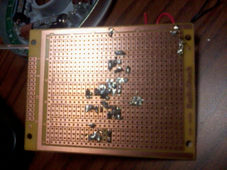
The terribly terrible soldering job. It works for what it's worth. Again I blame a lack of necessary supplies.
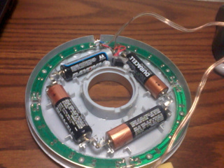
The light module that contains the LEDs and the batteries that power them. The 9v battery above only powers the timer circuit.
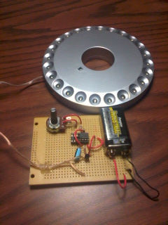
The complete set-up for the new project.