I like to go camping, and once upon a time it got dark and I was lighting the way with a flashlight when for whatever reason I swung it around quickly,and the resulting light effects looked cool. After a while I had the idea instead of swinging the flashlight to turn it on/off rapidly. I got up to about 3 Hz and it was cool for a while, but clearly a superior item could be made with aid of ingenuity, intelligence, and electronics (it surprises me how many people are content with just manually switching the light on/off. Boring!!!).The electronic design, in contrast, could easily go into the 500 Hz range.
More recently, I found cool articles on photography with strobe lights, and calculating velocity of rotating objects (such as a ceiling fan) with variable speed strobe lights. When I got a powerful LED array (24 bulbs, 4 AA batteries) I really had no choice but to make a strobe circuit. And sorry about the repetition; I couldn't find a good synonym for 'strobe'.
This project worked out pretty well. In terms of functionality it was what I expected. The only suggestion is if you're looking for a real strobe light, you should invest in actual components (well, or get a disposable camera with flash). Since this is LED-based, there is a bit of blur visible, unlike with a real strobe light (the flash is too long). Most likely though, using a smaller resistor instead of the 1k, should fix this to an extent. For a higher quality strobe, you may have to resort to using a digital controller, or a fancier resistor control (ideally, both R1 and R2 would change, otherwise the duty cycle changes along with speed - when speed is increased the LED will stay on for longer; for a good strobe the on time is very small and constant, only off time is changed).
I did not put a whole lot of time into packaging - it is functional and sturdy but not too pretty. Perhaps that makes it more imposing and thus more awesome. Ultimately though, nothing beats having a 'strobe speed' knob on your flashlight. Here are some photos:
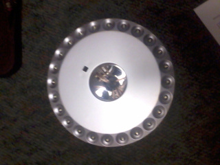
Top View. The LEDs on the outside (24) light up. In the middle, you can see the reflector of the old flashlight handle I attached, and some wires coming out of it. Those wires go to the circuit, which is inside the handle,and out to the controls on the outside.
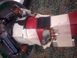
Side View. You can see the AA batteries which provide power to the LEDs.The 9V battery for the timer circuit is attached to the flashlight handle. It only powers the timer and not the LEDs. The switch on the flashlight now controls whether the 9V battery is in circuit with the timer, and the potentiometer next to it controls strobe speed. There is a small gray button on top of the handle, which is a switch for the 4xAA batteries, to prevent leaking through the transistor when it is turned off. Both switches must be on for the strobe to work.
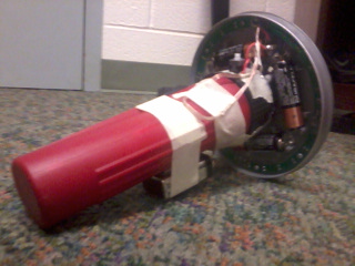
Full Project. The timer circuit is a breadboard inside the red handle.There are no batteries inside; the only batteries are the visible AAs and the taped 9V. The wires that control LED on/off are visible here; they connect to the back side of the silver disc and then go inside the red handle, connected to the circuit on the breadboard.