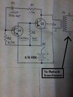
Note: this circuit diagram connects the battery to the 1:66 transformer, not the flyback. The output of this transformer is then fed into the flyback's primary.
This project came about as a consequence of a few old flyback transformers I found lying in the spare parts drawer. These were not old in the sense that they were not made recently, but rather that they had not been used for many months. As such, the reason they had not been used was because they had a new design which is nowadays found in all CRT devices, which is a combined transformer, secondary windings, and high voltage capacitor and rectifier for the output. Thus, driver circuits such as this would not be very useful with the new transformers. I decided to make something useful out of them, and remembered that I had the box left over from the violet laser which was now a lot smaller, and that is how this project arose.
Note: this circuit diagram connects the battery to the 1:66 transformer, not the flyback. The output of this transformer is then fed into the flyback's primary.
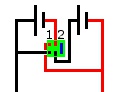
This is the set-up for the switch between parallel and series configurations for the batteries, using a DPDT switch. The switch is shown in green. In this case, each battery pack is 3 volts thus in position one, 3V are supplied and in position two 6V are supplied.
I started the project by making a breadboard version of the inverter circuit that outputs around 200V from 3V input.
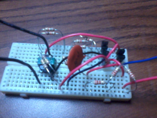
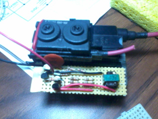
In the image, the 3V input is the two wires on the right (red is positive), then right-to-left are the 2 NPN transistors, 3 PNP, disk capacitor, and small transformer which is connected directly to the output wires going off the image to the left. The various resistors in the circuit were chosen to have a combined resistance that is required per specifications, for instance 3x2.2k resistors in series were used for a total resistance of about 6.5k.
After testing the proper power output using a voltmeter (placing a 300V capacitor with a diode on the output may help measure output voltage), I transferred the circuit to a generic PCB bought at RadioShack. The original board was rather large, so a small section was broken off for this project, as seen in the first image.
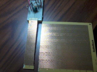
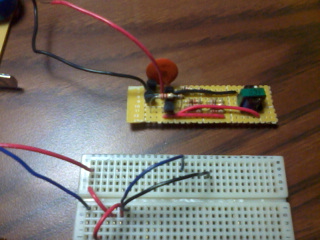
First, a section of a large PCB is broken off for the purposes of this project. After the circuit is transferred to the PCB, it is much smaller and neater-looking compared to the breadboard version. In the second image, only the 3V power input wires are attached to the PCB.
Next, the flyback transformer was made ready for use. Note that there are a bunch of wires coming out of the transformer; for this project only the thickest one (it will be connected directly to the top of a CRT if you open up a monitor) is useful and the other ones can be cut off with no negative impact. I am not sure what those outputs are, but most likely they are lower voltage sources. Further, since there are about 10 pins on the bottom, it was necessary to methodically find the primary winding and the ground. The positive output of the flyback is always the thick wire at the top. Using a continuity meter or ohmmeter, test what pins the first pin is connected to, then mark the first one and the ones it is connected to in one color. Continue this for the next unconnected pin, etc. This will make it fairly clear where the primary winding is, as it will have only two pins not connected to anything else - in this case that is the two blue dots on the right of the third image (already soldered to wires that will be connected to the PCB). All of the red dots, which comprise 6 of the pins, are various secondary windings which do not have any use for this project. After the project was built, it was possible to empirically determine which pin was the ground by the presence of a spark from the positive output. Note that in transformers with a built-in rectifier/capacitor (such as the one used), there will be no connectivity between ground and high voltage positive output, and the ground pin should not be connected to any other pins either. The ground is the pin marker with a black dot, in the top-left in the third image. There is also one unmarked pin, which serves an unknown purpose (maybe "heater output", but I have no idea what that implies). Actual datasheets for these transformers have been rather difficult to come by from my experience.
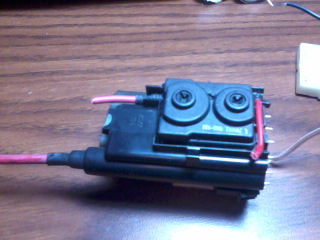
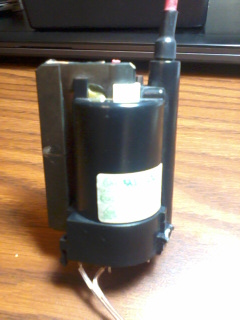
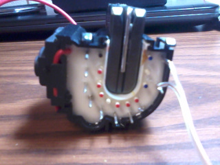
Two side views of the transformer, to give an idea of what it looks like. It is used in CRT displays to attract electrons to the surface of the CRT, so the thick red wire on top is positive (electron-deficient) while one of the pins on the bottom is the ground (electron-rich). The third image shows which pins are connected to each other, from which it is evident that the two pins on the right, marked in blue, make up the primary winding. These two pins are connected directly to the PCB transformer 200V output, and the entire set-up is seen in the fourth image.
Now it is necessary to make the portable power supply, out of four C batteries. Two 'packs' of 3V are made by connecting two batteries in series and taping them together. The two packs are independent of each other and can be connected in parallel or in series, per the second circuit using the DPDT switch.
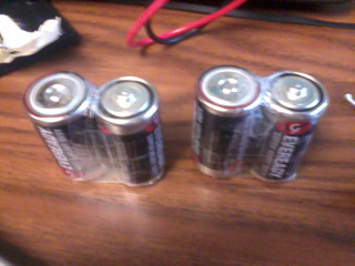
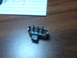
The two 3V battery packs, each made of two C batteries. The + of one battery is connected to the - of the second one. The second image is the DPDT switch used for this circuit.
With the power supply available, it is necessary to find the ground pin on the flyback transformer. Connect the 3V battery pack to the PCB and move the high-voltage wire so it is very close to touching the pins that were not connected to anything else. Look for a small spark, which will be indicative of the ground pin. The spark will not be more than about 1mm due to the low power output of the small inverter circuit. I cut off a part of the high-voltage wire at the top of the transformer and connected it to the ground pin while the other end was taped to the positive output wire to allow easier connectivity of the transformer and so it fits neatly inside the box. The two wires visible coming out of the box are the positive and ground. The wire connected to ground was colored black using a sharpie for easy identification as the ground from outside the box.
At this point, the only thing left is to fit the project inside the box. This particular box, bought at RadioShack and previously used for the Violet Laser, already contained an on/off switch at the top, an opening for power control, and an opening for the HV output. The pushbutton on/off switch (on top of the box) was wired in series with the parallel/series control switch to easily control power to the whole project; the parallel/series switch was attached to be accessible through the side opening of the box, and the transformer output wires fit through the hole in the front of the box. And that completes the project.
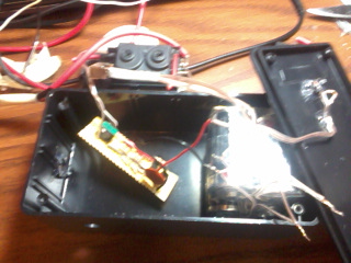
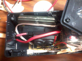
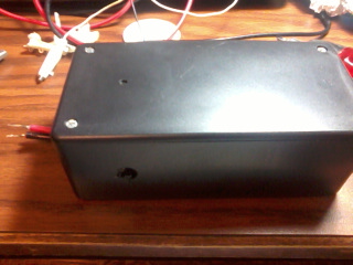
The batteries, power circuit, inverter circuit, and flyback transformer are placed inside the box and the portable HVDC supply is complete.
This project is admittedly satisfying because it allows one to answer "What would happen if there were a few thousand volts applied to _____?" rather easily. The project construction turned out sturdy and can be used in any direction. Also, the C batteries are large and should provide many hours of use when connected in parallel considering the relatively small power output. This also might be a consideration if more power is necessary (although with a HV capacitor this seems to be quite a potent source); in that case the entire driver circuit should be revised. From destructive testing, the tiny transformer can handle quite a bit (up to 17V input I believe) but the duty and life cycle decreases, and if the transformer goes, all the transistors will also likely get destroyed.
First, a test of conductivity in air. It does make small (<0.5cm) sparks in air, and at 6V the spark can burn paper and cut through shrink-wrap plastic. With a large aluminum metal plate (a can might work) a faint sound was heard when the plate was connected to only the positive voltage output; likely due to effects of electrons traveling through the air to ground, the sound of which was amplified by the aluminum plate.
The next item on the list is a fluorescent bulb, connected directly to the output wires from the box.
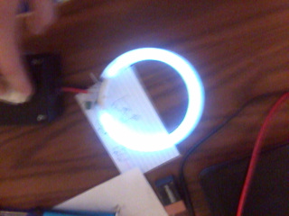
The fluorescent light test is successful - this is indeed a high voltage source.
Next I tested a few LEDs, which amazingly lit up only when the proper polarity voltage was applied and could stay lit continuously under high voltage, however after that test the LED was useless with regular batteries.
At 3V input, a continuous shock from the transformer output can be felt easily (however with any separation between the wires and the skin a plasma channel is created and causes small burns). I have not tested 6V output for continuous shock. Additionally, since the transformer contains an integrated capacitor, it can cause a slight instantaneous shock (less powerful than a static 'doorknob' shock) even after being turned off.
The fluorescent bulb shown above contained a small green capacitor (smaller than the disk capacitor in the PCB); I am not sure what it was meant for or rated for (update: used for starting the fluorescent tube, rated 630V at 0.0022 uF; the voltage output however is definitely much over 1000V as confirmed by a voltmeter (it arced through the voltmeter set for 1kV)) but I decided to hook it up to the HV output and as a surprising result obtained very bright and energetic sparks. Depending on the separation of the electrodes, something comparable to a taser resulted. With a bigger capacitor (maybe microwave capacitor?) the results might be quite interesting. This small capacitor was enough to somehow completely destroy the electrodes in a xenon flash tube from a disposable camera; still not sure what happened there.
Further testing is left to the reader.