Flyback transformer winding
After making the portable HVDC supply using C batteries and a tiny transformer, I realized that much more current would be necessary to achieve useful effects. While the portable source was useful in its own sense by providing a low-current source (which could in turn be connected to capacitors for more fun), the sparks that it created were not entirely satisfactory. In hindsight they were pretty weak, but after building the project I had no point of reference. However I still keep the portable version around as a 'safe' HV source that I use for non-destructive testing.
While considering how to get more power out of the other flyback transformer I had lying around (from a thrown-out CRT, new model with diode built in) I thought of the idea of a resonant (LC) circuit being used with the transformer, that is connect the transformer winding to a capacitor and then drive it at its resonant frequency thus transferring power very efficiently. The idea I had involved winding the connection between the transformer and capacitor to a ferrite bar, along with a wire that controlled the gate current for some transistors. This would be set up so that when the power was flowing one way across the transformer windings, the power source would be applied to the capacitor in the same direction, effectively driving it at a resonant frequency. When the power would be flowing the other way (due to capacitor charging then discharging), the magnetic field of the ferrite bar would change and this would cause a different set of transistors to turn on, which would reverse the direction of the power source applied across the capacitor to again drive it at its resonant frequency. This idea sounds like it would work (and probably has been done already, I just don't know what the circuit is called), however before I had a chance to experiment I found the so-called ZVS driver (zero voltage switching) (technically a Royer oscillator) which basically does the same thing using MOSFETs instead of transistors and a center-tapped winding instead of a ferrite bar. This circuit is good because it has such low energy losses, it can carry huge currents with minimal heating. I have confirmed this experimentally. Additionally, it drives the transformer at its resonant frequency automatically (ie without tuning) which is good for efficiency, and when the high voltage is not being used it takes very minimal energy to maintain the oscillations. Overall a great circuit; thanks [teravolt.org] for getting the technical details on the circuit and making easy diagrams. Maybe I'll get to do that once I actually learn some electronics theory..
I built a modified version of the ZVS driver. The linked page includes a circuit diagram. I will make my own when I have the time, as the components and configuration I used were a bit different.
One of the conceptual changes from the portable HVDC source was creating my own winding around the flyback transformer. This increases efficiency and makes the circuit easier than having two transformers in a cascade as was done previously to get the 120V required for the built-in primary on the flyback. Other than that, the use of MOSFETs and a resonant circuit greatly increases power handling capability compared to the single-frequency transistor oscillator used in the portable source. In order to provide this circuit with all the power it needs I connected it to a 12V car battery. I also tested it with 12V wall transformers (rated for 1 amp) and those did not stand a chance. You will need a car battery or similar in order to use the ZVS driver at its full potential.
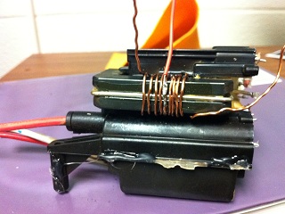
First, wind a primary around the flyback transformer. I used wire from an inductor in a mains line filter from a computer power supply - this wire is thick and has a coating of insulation. There are 5 turns on either side of the center tap to get a higher voltage output.
Flyback transformer winding
Second, find heatsinks for the MOSFETs. There happened to be an old UPS lying around so I used heatsinks from there. They are completely unnecessarily huge for this task but I was too lazy to cut them to size. Note that both MOSFETs should not be mounted to one heatsink. Keeping the mosfets cool is important to consider as it is no fun to have a high voltage source fail mid-use. It is also important to consider the physical design of the cooling system as I learned in a failed air cooling base attempt.
Third, construct the circuit. I did not have a good enclosure for an actual PCB so this one ended up on a breadboard. Below are two views of the breadboard. On the left and right are the two huge heatsinks with one MOSFET mounted to each one of them. Towards the top, the two gray rectangles are the capacitors. I used 2x1KOhm resistors in parallel for 500Ohm total resistance since RadioShack did not have any other resistors that could handle the necessary current. Those are the four large gray resistors in the middle of the breadboard, one pair for each MOSFET. I used two fast diodes in parallel in place of the UF4007s on teravolt's page and they work fine. Instead of using the Zener diodes I hoped for some good luck and it has worked so far. For the inductor on the center-tap I used something that looked approximately like the inductor on teravolt's page, I am guessing 100uH; this also came from the old UPS.
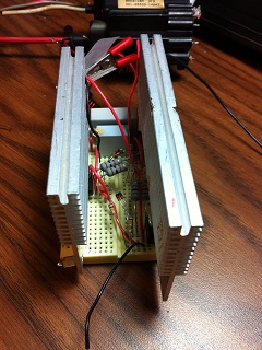
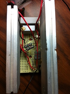
The ZVS driver on a breadboard, top and side views. The flyback transformer is connected in the background.
The HVDC source is now usable, but for continued service you should add air cooling. Even the unnecessarily huge heatsinks I had (with thermal compound used to connect the mosfets) heated up appreciably while I was using the circuit. On that note, holding out long sparks continuously seems to draw the most current (as opposed to shorter sparks). With a computer fan wired to a 12V wall transformer carefully mounted on top of the heatsinks so it cools the mosfets and other electronics (blowing air downwards), this HVDC source is ready for experimentation.
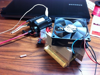
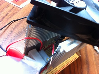
The complete setup with the computer fan added. Perhaps those heatsinks weren't entirely unjustified, since they do heat up under full power! With the fan on, the transformer can be used at 100% duty cycle.
I was very happy with the performance of this driver. A great entry to real high-power projects. The spark from the transformer is hot enough to melt metals (including staples, regular wire, heater wire (nichrome - melts at 1400C!), and even a spot in a penny) and create other fun effects. In a DC arc, the electrons go towards the positive end (the thick red wire on the flyback) but high-temperature air ions (thousands of times heavier than electrons) in turn go towards the negative end (ground pin), so whatever is connected to ground heats up incredibly while the positive wire on the flyback only gets relatively warm. This principle could be naturally used with more power to create a welding machine. If an arc is made to water in a metal container (water connected to positive), the water gets an ozone-like flavor (maybe it is ionized?). I've had difficulty finding capacitors that would work with the high voltage here; perhaps MMC would work. I am sure this could be used to make x-rays but I don't have a vacuum tube. Overall it is just too tempting to burn stuff with this sort of power output so not much along the lines of scientific research has been done.