This project started when I obtained a free GM counter kit as part of an event held by my department. The kit itself included a 10-cm long GM tube and a circuitboard with components that are to be soldered onto it. The circuit operation is fairly straightforward - it is powered by a 9V battery, an IC is then used to make a boost converter that generates about 400V required for the tube, the pulse in voltage from a radiation event activates a 555 set up in astable mode which creates a longer pulse, and this longer pulse is used to activate a piezo speaker and also an op-amp integrator that turns an LED from green to red as radiation rate increases. While the circuit operates reliably, it seems to me that some features are unnecessary, like the integrator and a dedicated 5V power supply. In any case, the indication provided by the speaker and red/green LED is certainly lacking for any decent research purpose. This project aims to improve the data collection capability of the GM counter by pairing it with a microcontroller that will accept pulse input. This will provide useful features such as background subtracted counting, integral counting, radiation logging, high radiation alarm, and a pseudo dose rate monitor.
The project as detailed here uses a prepared circuit board, but the circuit is simple enough to be constructed on breadboard.
The construction is fairly straightforward: the pulse output of the GM circuit is connected to an interrupt-handling pin on the microcontroller (pin 2 on the Arduino Micro), and then an interrupt is set up in code to increment a counter variable every time a pulse arrives. Beyond that, the hardware side includes a voltage divider to allow detection of battery voltage by the microcontroller, a few transistors to allow the microcontroller to turn the LCD backlight and speaker on/off, a clamping diode to ensure the pulse from the GM circuit does not exceed the rating of the microcontroller, and connections to input devices (four buttons and a switch). The Arduino Micro conveniently has built-in pullup resistors so there was no need to even worry about that. Despite the conceptual simplicity, this still ends up involving a lot of connections, and I managed to use all 13 pins on the Arduino board, which led to a bit of messy wiring.
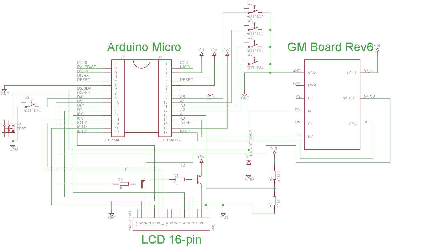
The circuit diagram for GMX, depicting how the Geiger counter board is connected to the Arduino along with other peripherals.

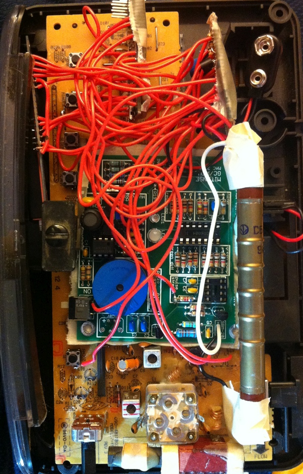
The original GM board, with GM tube seen in back, and red wires added to connect it to the microcontroller.
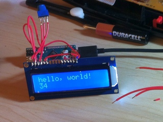
Testing the LCD with the LiquidCrystal library 'HelloWorld' example. The LCD was connected following instructions on adafruit.com.
The next question is what frame to use for this project? I needed something that has many buttons, some sort of opening to allow betas to enter, and a space for a display. Luckily I had an old digital alarm clock that was just big enough to comfortably fit all the required components! After moving around some of the wires to get everything to fit, I got a working alarm clock/GM counter! Hopefully this will look less alarming than an obvious GM counter if I just carry it around while collecting data. I replaced the power cord with a USB cord to program or download data from the microcontroller, and connected the existing buttons in the clock to the pins on the microcontroller, allowing me to interface via buttons like Hour, Minute, and Snooze, as well as an on/off switch and another switch that will be used to activate a low power 'sleep mode'.

Wiring all the components together (including the alarm clock circuitboard on the bottom to get access to buttons) and getting it to fit in the case.

An old alarm clock! Oh wait it's actually a GMX.
Most of the effort in this project is in the software, to enable rapid and straightforward analysis of radiation data. The following are the main features I have been interested in seeing in detectors I have used:
The GMX software implements the above features, although not all have been tested with a proper calibrated source.
To test the logging functionality, I took the GMX alarm clock on a flight from Tokyo to DC. It got through security without a problem, and in any case had a 'clock' mode for anybody doubting its actual function. In fact, I took that opportunity to log radiation levels inside the x-ray scanner. They were quite high, reaching 400,000 counts per minute, or 20,000 times the background dose of approximately 20 counts per minute (this is radiation that any object on the ground will receive due to energetic particles from space and within the earth).

GMX logging radiation levels inside an x-ray machine as a function of time as it was passed through the machine.
But perhaps what will be more surprising to readers not familiar with sources of ionizing radiation, is that during the flight which was around 30,000 feet elevation, the radiation levels increased up to 250 counts per minute, or slightly over 10 times the background radiation on the ground! Airlines workers, who spend a lot of time in flight, can actually get a higher radiation dose than workers at a nuclear power plant! The reason for the increased radiation is that a lot of background radiation comes from energetic particles in space (also a reason astronauts get a higher radiation dose). As the plane climbs higher, there is less atmospheric air protecting the plane from cosmic radiation, and thus the radiation dose increases.
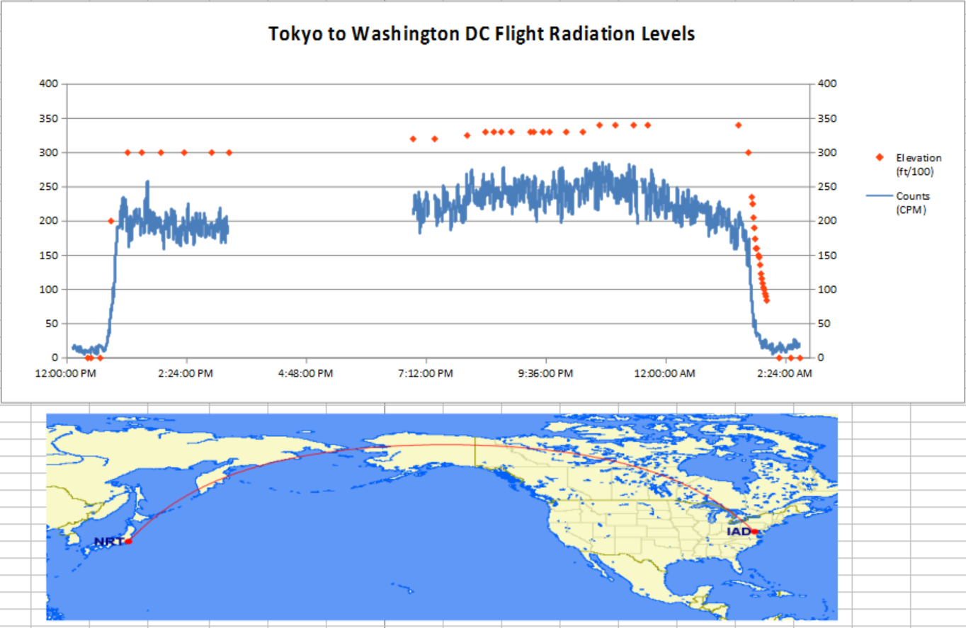
GMX logging radiation levels for a large part of the 12-hour flight from Tokyo to DC. The logging could have been done on a single battery but I switched to a new one midway to ensure no data would be lost. The red dots represent elevation in units of ft/100, on the same y-axis scale as the counts per minute shown by the blue line. The map underneath presents an approximate path of the airplane.
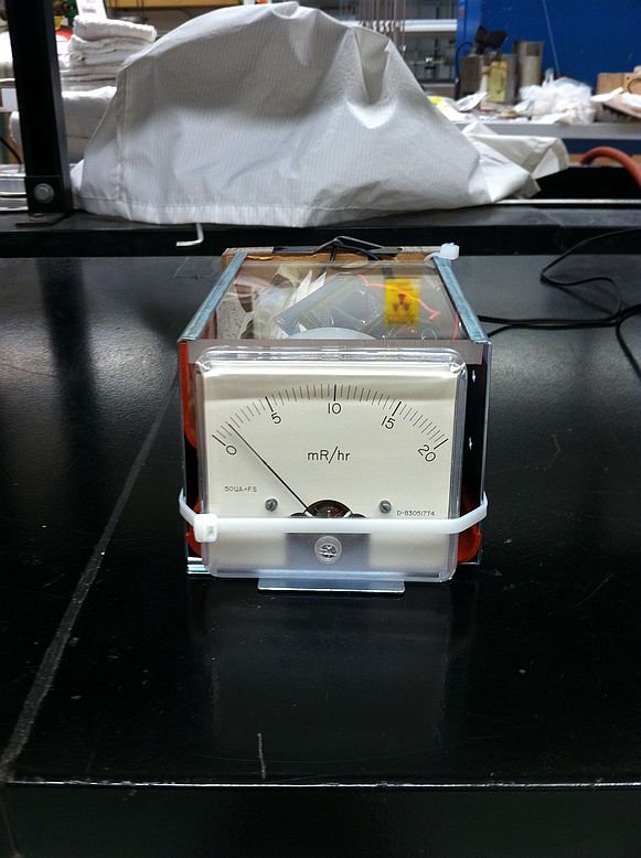
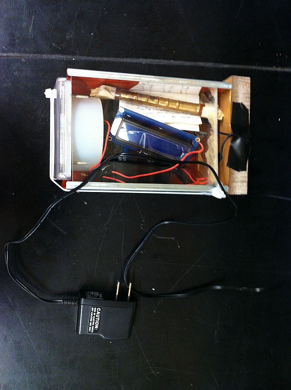
After some more measurements in the form of an alarm clock, it was time for the GMX to take on a more stationary appearance. The main components of the circuit were repackaged in a metal box and an old analog panel meter was used as the live readout. The panel meter was labeled as mR/hr, which is a fairly high unit of radiation (the annual background dose is about 300 mR), so I set up the dial to display the counts per minute instead. A large 10 mF capacitor is used to integrate the counts over tens of seconds so the reading on the meter appears stable. Photos are linked below.