Working Violet Laser: 405nm, ~100mW optical output
October 27, 2011
This is my first working violet laser. My first attempt and other considerations are on this page. A remake of this circuit to minimize size is here.
Idea
I won't go into too much detail here because I already outlined this in the original laser page (link below title). Basically, my original attempt did not work out so I ended up re-trying, and everything turned out well.
Warning
This laser is powerful enough to blind. Never look directly into the diode, even if it is not collimated - I looked into it at a very low power output (2mA) which felt comparable to looking directly at a household light bulb. To test the diode, shine it onto an object such as a piece of paper, since diffused light (the laser dot on surfaces) is safe to look at for reasonable power output (100mW), such as what is suggested on this page. Using the lens to focus the laser into a small spot will greatly increase apparent brightness and may be unpleasant to look at. Be aware of any mirrors or reflective surfaces which may redirect the beam unintentionally (the glass in windows reflects lasers quite well).
Note that this diode outputs light in the near-UV range, which makes it seem a respectable amount less bright than it actually is. This is evident by shining the laser onto a fluorescent material (such as paper), which will result in a bright blue rather than violet light.
Credits
The output current regulator, or "laser diode driver", which is the main part of this project, is based on the circuit in this post at laserpointerforums.com. There is a reference to a circuit diagram, made by rog8811 of same forum; this image is accessible from the main forum thread.
A lot of useful techniques can also be found at the Violet Laser page on styropyro.com. Lots of information for testing diodes and pretty much anything else laser-related: Sam's Laser FAQ.
Supplies
The driver circuit was originally designed by Daedal of laserpointerforums.com. On this page I list some useful tips I gained from building this circuit, since I've had no prior experience and this might help others in a similar situation.
- 405nm Laser diode (I would recommend the PHR-803T or PHR-805T variety)
- Aixiz Module for 405nm diode (5.6mm) - available at modwerx
- Some sort of case (I used a project enclosure from RadioShack)
- 2x 47ohm resistors
- 25ohm variable resistor, available at RadioShack
- LM317 voltage regulator, also available at RadioShack
- Wires
- On/off switch
- New 9V battery (the diode doesn't lase below a certain voltage threshold so used batteries may cause frustration)
- Ammeter and voltmeter for testing; 250mA and 25V ranges respectively, or similar
- Optional - key mechanism for safety
Construction
- Design the driver circuit per the visual representation [drawn by rog8811], substituting two 47ohm resistors in parallel for 2x10ohm, and 25ohm variable resistor for 100ohm variable resistor. This will give an accurate full range of 50mA - 100mA for the 805T diode, and should be very similar for 803T. The way I constructed this, the variable resistor control goes outside the casing so resistance (and thus current) can be adjusted during use. These resistor values will keep the diode in a good zone for its lifetime (if the variable diode is at either 0 or 25). The diode can handle more current, but this will reduce its lifetime. Since I currently have an extra diode lying around I may do some destructive testing, but I would like to have one laser to last for a while. To go beyond 100mA, use less than 47ohms in parallel, but be sure to test the current output first to avoid killing your diode.
- Test the driver without the laser diode (procedure below)
- Take apart the Aixiz module. It should have at least five parts, the grooved ring that goes around the lens, the lens itself, the diode/lens holder piece (between the ring and the large hollow cylinder), a spring, and the large hollow part that can hold the diode driver if it is that small.
- Insert laser diode into Aixiz module. This procedure is best described at styropyro's site; link is in the credits above.
- Solder wires to the diode leads. Note that if your driver fits within the Aixiz module, you won't need to do this at all. I still haven't gotten a good working soldering iron, so I was content with soldering one lead and using the case for the other. Obviously my driver circuit is nowhere near fitting inside the tiny cylinder. Again, styropyro outlines how to do that right (although that project requires purchasing a driver). Be careful in this step to not overheat the diode. It should not be too difficult with the diode inside the module, but give it time to lose thermal energy between solder applications since the module will tend to heat up over time.
- Test the driver with the diode (procedure below) and find range of acceptable current
- Put together module, add switch, and enclose project
Testing Procedures
This was something I had trouble with, as I did not have much experience and do not have access to expensive testing supplies. Here are some guidelines:
First run: Testing without the diode
For this, the driver needs to be completely built. Connect an ammeter directly to the output, and connect a 9V battery to the circuit. Check the current output over all variable resistor values. The current should be 50mA to 100mA. If it is not, check resistance values. Higher resistance values (either fixed or variable resistors) will cause less current. Easy enough.
Second run: Testing with the diode
Warning: the capacitor in the driver stores charge which can destroy the diode. Before connecting the diode to the driver, be sure that the capacitor is discharged (touch the output wires together with battery off). Then securely connect the diode, because if it accidentally disconnects and reconnects while the battery is on the current from the capacitor will be bad. Only then connect the battery. When done, disconnect battery first, diode second.
Make sure the capacitor in the circuit is discharged by making a closed circuit. Then, securely connect (sorry about the repetition, this was probably the part where I messed up on my first try so I want to emphasize) the diode and ammeter in series. This way, the ammeter reading is equivalent to the current going through the diode. Set the variable capacitor to the value that yielded lowest current from the test above (re-do it if you don't know, it will be easier than buying a new diode). Then connect the 9V battery, and increase current via the variable resistor until you feel that you have enough power output. The best-lifetime current for the two listed diodes, from what I found online, is around 100mA. Coincidentally this is the maximum that the circuit configuration with the adjusted resistor values provides.
Expected diode behavior
For part of the testing I used a lab-type variable voltage DC supply. From this I found out that at low voltage (below about 6V) the diode acts much like a dim LED. It has its violet color but is quite dim. Around 6 volts, the light output characteristic changes dramatically, and it becomes bright. Note that the diode does not output a straight beam like one might initially expect from a laser (this is what the lens in the module is for) so it will look like a very bright LED without the module. The "very bright" part is the sign that the diode is not dead or malfunctioning. Another observation I made is that laser light, since it is monochromatic, makes styrofoam objects (like coffee cups) as well as some others, look 'fuzzy' when illuminated. There probably is a name for this effect that I am not aware of; if you are not sure what I am referring to try shining any laser pointer into a styrofoam cup. This characteristic is another sign that the emitted light is actually laser light.
Increasing voltage past the lasing threshold significantly increases brightness and current taken by the diode, until its breaking point, which I did not have the guts to find out.
In summary, if your diode looks dim even with the proper current from the first test above, do the second one and you will see it is barely drawing any current because the voltage is too low. Thus, a new 9V battery can go a long way.
If a diode is dead, it will be very dim even above 6V and while drawing significant amounts (50mA+) of current. It may not light up at all. The most important thing is the significant current draw. If the diode looks dim but is only using 2mA most likely there is a problem with the power supply, such as not enough voltage or current. This has happened to me in an attempt to power the diode with a weak battery (<5V), nearly leading me to think the diode was dead, because the output current without the diode was 50mA. Testing the diode in series with the ammeter (procedure 2 above) I saw that in fact it only drew 2mA at the supplied voltage.
Photos
Construction
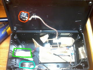
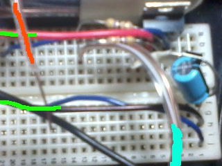
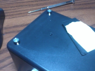
On the left, the inside view of the laser 'box'. On the right, close-up of the driver circuit. The orange outline is the on/off switch, green outline is laser module, and blue outline is variable resistor. The wires are outlined to match the component they are connected to. The circuit itself is pretty simple, consisting of the two resistors, LM317, diode, and capacitor, all of which are visible in the photo. This is connected through the switch to a 9V battery that is attached to the inside of the box and touching a side of the breadboard.
Completed project
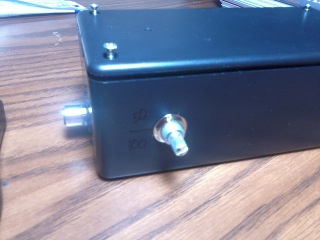
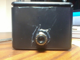
Angle, front, and top views, respectively. At this point the top is not bolted down. The laser output, in the front of the box (head-on view pictured in the middle), is the Aixiz module secured in a drilled hole with some hot glue. On the left of the module, the variable resistor control is accessible, and the case is labeled '50' and '100' so it is easy to tell the current power level. The switch is visible in the top view; I used a pushbutton that was about half as 'tall' as the layer of plastic, so I made an implement that would extend into the hole to press the button; this is the white object pictured on the right side of the top view photo. Doing this provides a level of safety, since most little kids will not be interested enough to find a way to push the power button.
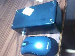
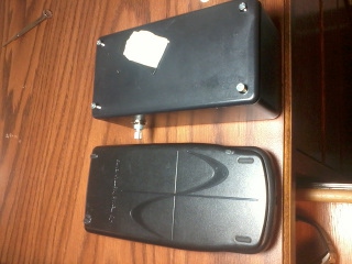
Size comparison - first, to a wireless computer mouse, second to a TI-83+ calculator. On a side note, how does TI still manage to sell those things when ridiculously more powerful and visually appealing multimedia devices cost much less? Somebody really needs to come out with a viable competitor product; touchscreen and color would be nice.
Power output
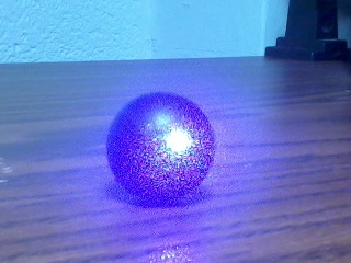
This is a black bouncy ball, subjected to a concentrated laser beam at 100mA. The surface easily smokes, but it takes a good amount of time to make any sort of visible deformation. I tried to capture the smoke in this photo, but the laser is too bright.
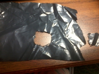
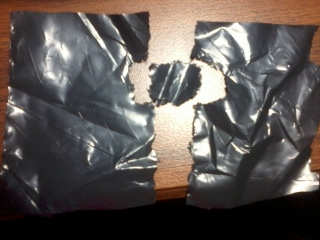
That is me creating an abstract art piece, using the focused laser beam at 100mA, and a piece of plastic cut out of a black leaf/trash bag. The laser certainly can cut through this, but at least at this power it takes a steady hand to make an accurate cut. The material needs to be moved quite slowly, and kept at the proper distance from the lens. Increasing the power output will allow one to move the material faster and thus may provide smoother cuts.
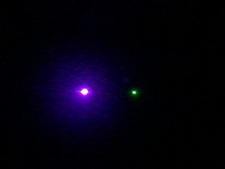
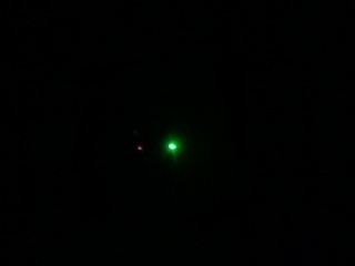
A comparison of brightness between the three lasers I currently own. First photo is violet vs green, second is red vs green (see that little dot to the left of green?). Violet at 100mA, green at an estimated <50mA, and red at about 5mA. The red one is a regular OTC laser pointer, while the green one is supposed to be <5mW but from empirical observations seems to be more. The output power of violet is in the 75-80mW range. Moral of the story: if the only laser you have is a red pointer, you are missing out big-time.