Violet Laser Mini-Version
December 10, 2011
Idea
After completing the violet laser as described in the previous post (link below title), I was not particularly impressed with the laser performance so I tested the current output with an ammeter and realized that the power output was well below the expected 100mA. This may have been partially due to the battery drain caused by previous use of the laser, or due to improper calculations. I updated the circuit to output a full 100mA, which yielded a much better performance. To take it a step further, I decided to place the entire circuit on a PCB, since there are only four required components. The build was successful and satisfying, as I ended up with a higher-powered laser in a much smaller space than before. Now the design is easily hand-held, and is very similar to the size one might attain by ordering a manufactured PCB that is very small (however with that, it is not possible to easily control the output current, a feature I was looking for).
Circuit
The driver circuit is the same as in the previous version, taken from a laserpointerforums.com post titled 'DIY Laser diode driver'. However due to the low power output of the previous circuit, in this one the constant resistors were taken out entirely and the only resistor was a variable one, 0-25 ohms. For comparison, in the last build two 47ohm resistors were used in parallel for a minimum of 23.5ohms resistance with the potentiometer set to zero. With this setup significantly more power is attainable, but it calls for careful current output testing before using the diode as setting the resistance to zero will essentially give full current (which may be appropriate depending on battery voltage).
Build
To actually build this, I used a large RadioShack PCB I had lying around, from which I broke off a section at one edge that was five rows into the board, which resulted in a long and relatively narrow board. The width was just enough to attach a 9V battery and the large potentiometer. The circuit, consisting of an LM317, capacitor, diode, and potentiometer, connected to the battery and laser diode, was designed on the PCB in order to minimize space. A trick I found useful was to use components with long leads to double as wire when connections are needed - the leads once soldered can be bent and connected to other components. The button and laser diode were mounted on the metal side of the board, the diode in order to contact a negative voltage point (the assembly is case-grounded, so it is purposefully attached above an exposed row of ground-connected solder points), and the switch in order to be on the opposite side of the 9V battery for easy access.
After the soldering was done, large components such as the laser module, potentiometer, and battery were attached by hot glue and then held with masking tape. A small part of the PCB was left unused and was cut off. The final product ended up remarkably sturdy and small. Considering some of my previous experiences with PCBs, this went over very smoothly and worked a lot better than I expected (and on the first try!), which is why I am so happy about this project.
Power
The new power output of the laser merits a mention. In the previous post I discussed how it could cut dark plastics and make some smoke. Once I got the full 'OK for diode lifespan' power output at 100mA (the diode can take up to around 200), the laser could easily cut plastic bags, create smoke on wood and paper surfaces, pop balloons, and light both paper and wood matches. That is a very worthwhile improvement.
Photos
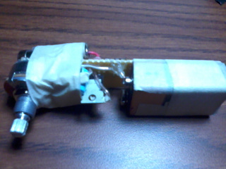
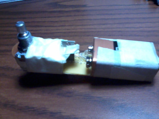
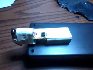
Side view and top view, where the battery and potentiometer to control current output are visible. The entirety of the circuit fits between the battery and the potentiometer and is almost entirely covered by the masking tape that is used to keep the laser diode in place. The LM317 is nonetheless visible in the side view. The laser diode itself is on the opposite side of the board from the potentiometer and has a red wire connecting to a positive output while the case is connected to ground.
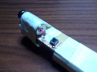
Bottom view, in which the power switch and laser module are visible.
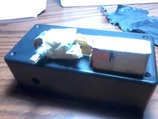
Size comparison to the old box design. The new design is a lot smaller and more portable, and more than that it is fun to show to others (since it looks very home-made unlike the box) and knowing that I am able to make a project this compact is quite satisfying for me. But in addition to that, while being smaller it is in fact much more powerful!