Derivation of centripetal force based on integral action of the force over a half-rotation.
This quest started from an attempt to explain the functioning of a playground swing. (Note: A more complete treatment is given in the 2022 update under Swing Acceleration) On a swing, it is possible for the rider to gain angular momentum, but short of pushing off the ground there seems to be no way to accelerate in the tangential direction, which leads to the question: what allows the acceleration that is experienced by a rider on the swing? (Similarly, due to the conservation of angular momentum, where does the excess angular momentum come from?) (July 2021: Another interesting take on the topic can be seen here, and that derivation highlights the impact of the rider's angular momentum about his center of mass - something I can tell is important from how it feels to accelerate on the swing; in the context of my solution below, this allows the use of angular momentum to exert an accelerating force with a lower linear displacement at either end of the swing cycle) For this the concept of a rotating reference frame is introduced. We will use as a starting point the linear-motion version of Newton's laws (F=ma and a free object moves in a straight line) and assume a constant downward gravitational force. Also, only the 2D case is considered here (3D will give rise to the gyroscopic effect). We will find a general representation of a rotating reference frame, that will answer the above questions, as well as others such as the path that an air molecule would take after exiting a centrifugal blower.
The observation points used here are two-fold, one is the view of an observer watching the swing and the forces exerted by the stationary structure, while the other is the view of a rider on the swing and the forces that are apparently stationary in that frame. What will appear as a tension force (of the chains holding the swing) in the first view will appear as a centrifugal force in the second view. This dual approach demystifies the 'fictitious forces' associated with a rotating reference frame and shows that they are a manifestation of real forces as observed from a stationary frame. Thus the total magnitude of all the forces in both frames need to be equal for the scenario to be physically viable.
The axis of rotation, in this case the bar to which the swing is attached at the top, can be agreed upon by both the stationary and swinging observers, so this will serve as a reference point in the 2D frame. A polar coordinate system is adopted, so that forces experienced by the rider can be defined as either radial (along the direction of the chain) or tangential (along the direction of the swing's motion). The rider's motion will also be composed of these two components. Even at this point we see the paradox that the chain is always perpendicular to the tangential direction, and thus can contribute no acceleration towards the swinging motion, so how does the observed tangential force arise? At the beginning the rider can push off the ground which will lead to tangential forces, but later the rider somehow continues to accelerate without touching the ground.
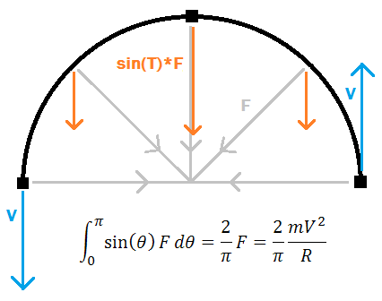
As mentioned before, we take as given that an object in motion tends to follow a straight line path. Thus in order to make an object go around in a circle, it must be accelerated somehow. Since the circle looks the same with any rotation performed on it, we reason that the force acting on the object must also be uniform during its motion. If an object is moving in a straight line, acceleration along its line of motion clearly will not make it change its direction so it travels in a circle (but rather increase its velocity or change its direction in the imaginary time-space). In the 2D frame there is only one direction perpendicular to the direction of motion, so the force must be acting in that perpendicular direction. We can check the magnitude of this force by considering an object of mass m moving along a circular path at a distance R from the desired axis of rotation with velocity V, and check what force will be required to accelerate the object during one-half of a rotation where its velocity vector changes by 180 degrees.
Derivation of centripetal force based on integral action of the force over a half-rotation.
In the rotating reference frame, in addition to the linear velocity V it is useful to define angular velocity, dT/dt (where T is the angle 'theta'). The conversion between the two is fairly straightforward if we see that the centripetal force, always perpendicular to direction of motion on a constant radius path, cannot change the magnitude of V. Thus an object going in a circle with velocity V will traverse the circumference 2*pi*R in time t=2*pi*R/V. This corresponds to 2*pi radians, so dT/dt=2*pi/(2*pi*R/V)=V/R and similarly V=R*dT/dt. Substituting this into the formula for centripetal force we find F=mR*(dT/dt)^2
The force found above is what is required to keep R constant, but it is reasonable that any force applied beyond that amount will serve to cause changes in R like a regular acceleration. Thus we find the externally observed radial acceleration d^2R/dt^2 = (F_r+mR*(dT/dt)^2)/m, with F_r being the real applied radial force (force exerted by swing chains). This shows that in order to maintain R constant (d^2R/dt^2=0), F_r must equal -mR*(dT/dt)^2 (=-F) in other words that is the 'pulling' force the swing must exert to keep the rider moving along an arc. Strangely, due to the radial system, linear motion laws no longer apply at face value - that is d^2R/dt^2 is a radial acceleration, but this is no longer equal to F_r/m (from Newton's F=ma). Thus the steady state situation of an object going around in a circle is that there are radial forces but no radial acceleration, that is the rider feels a 'centrifugal force' while swinging but does not move any further away from the swing axis. (As an aside, an object in orbit about the earth moves in a circular path but feels no radial forces, suggesting the notion of curved spacetime).
So far, only forces perpendicular to the direction of travel have been considered. In the swing system, there clearly must be other forces, parallel to the direction of travel, that allow the rider to accelerate and gain height. The origin of these forces is not as intuitive as the centripetal force and requires a mathematical treatment. The physical origins are suggested later in the article. We begin with a picture of an object allowed to move in a general sense, with both a radial and a tangential velocity V_r and V_T respectively. An infinitesimal moment of time (dt) is taken as a representation of the effects of the forces, and in this time the object moves through angular displacement dT = dT/dt*dt. We center the representation about the angle dT/2 for symmetry in the analysis.
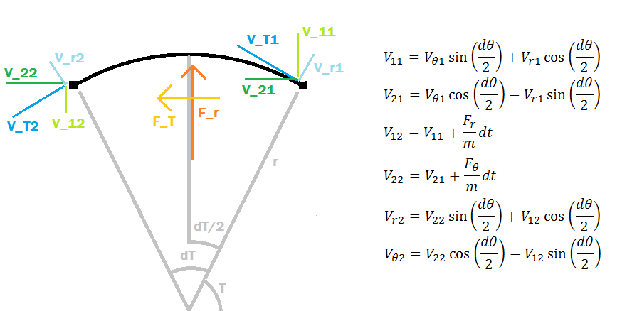
The set-up for the derivation of the full 2D rotating reference frame, with tangential and radial forces. A symmetric system (in terms of dT) is chosen to simplify the mathematical expressions.
In this system, the radial force F_r acts vertically and the tangential force F_T acts horizontally (they are averaged over dT). To establish the effect of these forces, the original velocity vector (V_r1, V_T1) is transformed (by basis rotation of dT/2) to an intermediate vector (V_11, V_21) with a vertical-horizontal basis. The forces (F_r, F_T) act on (V_11, V_21) to result in (V_12, V_22) final object velocity, which is then further transformed (by basis rotation of dT/2) into the final vector (V_r2, V_T2). The associated formulas are in the above figure. From the nature of these transformations, it is already evident that the radial and tangential velocities and forces are not independent like their counterparts in the linear motion frame. Nonetheless this analysis is at its basis a conservation of linear momentum, so the relation to a linear system should be made clear through it.
Solving the rotation of basis transformations, we obtain expressions for V_r2 and V_T2 in terms of V_r1, V_T1, F_r, and F_T. We desire to find the observed acceleration of the object (rather than the forces, which we have seen are not directly related), namely (d^2 R)/(dt^2) and (d^2 T)/(dt^2). In the infinitesimal system used here, d^2 R/dt^2 = (d/dt) V_r = (V_r2-V_r1)/dt, and similarly (d/dt) V_T = (V_T2-V_T1)/dt. Setting cos(dT/2)^2 = 1-sin(dT/2)^2 in the expressions for V_r2 and V_T2 makes simpler expressions for the acceleration equations listed above. Solving for these gives the desired result.
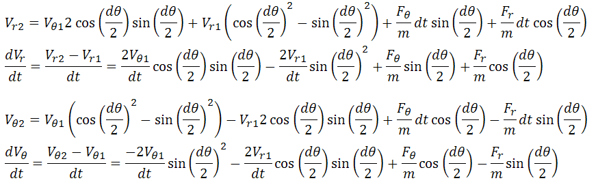
The radial and tangential accelerations are found, but the resulting expressions are not very enlightening.
The expressions are still quite confusing and have effects from all the variables. Due to the infinitesimal assumption, we can make simple approximations to the sine and cosine functions, and then rewrite them in terms of dT/dt which is a non-infinitesimal variable.
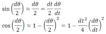
The sine and cosine functions may be replaced by the first terms in a Taylor expansion for small dT.
Substituting these into the above equations allows the discarding of terms that have one or more dt remaining, since in the limit as dt goes to zero these terms will disappear. This greatly simplifies the equations and gives the resulting expressions for accelerations in the rotating reference frame.
Simplified expressions for the radial and tangential accelerations. The tangential acceleration is still in terms of actual (linear) velocity rather than angular velocity though.
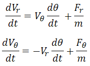
Further, recognizing that V_r=dr/dt and V_T=(dT/dt)*r, we can rewrite the equations entirely for angular accelerations d^2 R/dt^2 and d^2 T/dt^2. There is a bit of mathematical trickery involved with taking the derivative of V_T (product rule):
This expression converts the tangential acceleration into units of angular velocity.
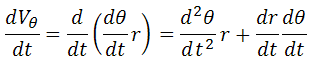
It is fascinating that this operation conserves the impacts of the different variables although the form and interpretation of the equation are changed noticeably. This gives the final result.
These two equations describe the general 2D rotating reference frame as viewed by a stationary observer. F_r and F_T are real forces that may do work and expend energy, and thus will be agreed upon in both the stationary and rotating reference frames.
We may recall, from the earlier straightforward derivation of centripetal force, that we found d^2R/dt^2 = (F_r+mR*(dT/dt)^2)/m with the assumption that extra radial force will act as a simple acceleration. The confirmation of this result in the detailed derivation shows that this is the case generally. The detailed derivation, however, gave the additional finding of d^2 T/dt^2.
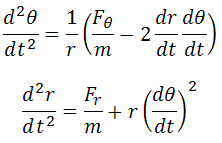
Further confirmation of this result should be done by considering five cases: stationary object, object moving only radially, object moving in a circle (accelerated radially), object accelerated tangentially, and free moving object. The self-consistency of these systems, as well as their correspondence to observable phenomena when approached using the two acceleration equations is verified below.
In the first case, r and T are constant, and dr/dt and dT/dt are both zero. The equations for the accelerations give zero as required.
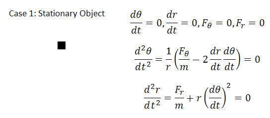
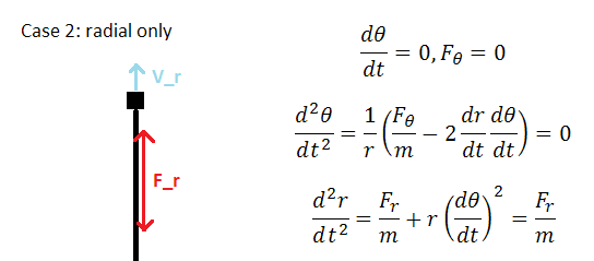
In the second case, dT/dt is zero while dr/dt is nonzero, and no tangential forces are present. The equations result in zero angular acceleration and any radial acceleration can only be due to radial forces, as reasonably expected. In essence this is a reduction to the linear system, as now d^2 r/dt^2 = F_r/m.
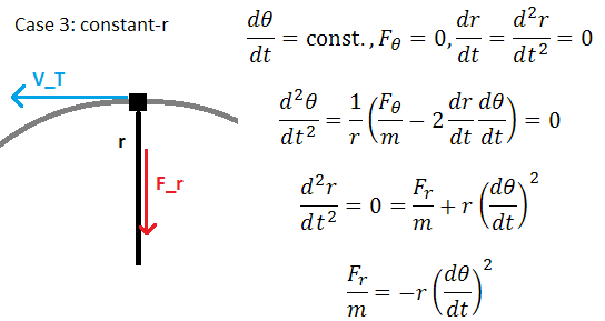
In the third case, dT/dt is taken to be nonzero and constant, and dr/dt is taken to be zero. This requires that d^2 T/dt^2 = 0 and this is true in the absence of tangential forces. Further d^2 r/dt^2 is required to equal zero, which can occur only when F_r/m = -r(dT/dt)^2. The expression is stating that to travel in a constant radius circular path with nonzero dT/dt, a centripetal force of this magnitude is required (scaling linearly with r and quadratically with dT/dt), which is a welcome result as it matches the earlier half-circle derivation as well as real-world experience.
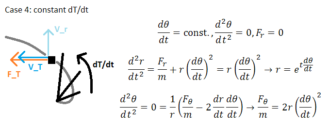
In the fourth case, F_r = 0, dT/dt is a nonzero constant, and F_T is expected to be nonzero. This situation is similar to what an air molecule experiences in a centrifugal fan, where tangential acceleration causes air to move outwards as a result of the virtual centrifugal force.
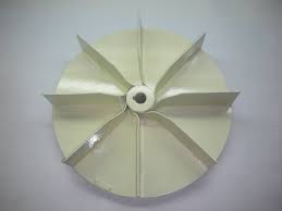
A centrifugal blower with impellers such as this is a real-world example of motion due to tangential acceleration in a rotating reference frame.
With F_r=0, the equation for radial acceleration becomes a differential equation, the solution of which is the exponential of t*(dT/dt), so r(t)=exp(t*(dT/dt)). We then find dr/dt=(dT/dt)*r(t) and with d^2 T/dt^2 taken to be zero (since dT/dt is constant) we use the angular acceleration equation to determine the magnitude of F_T, F_T/m=2*(dT/dt)^2*r(t).
Therefore both the force exerted and the radius of the object increase exponentially, as does its velocity. This suggests that centrifugal fan impellers do not need to be very long to be effective, and furthermore that exiting air has equivalent radial and tangential velocity and thus emerges at a 45-degree angle to the tangent line of the impeller disc. A computer code was written that simulates this motion with only linear momentum laws, and the results were found to agree with this derivation.
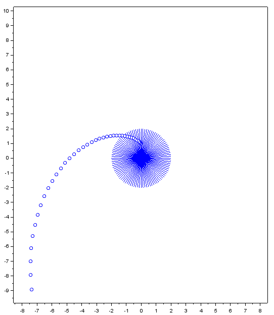
A simulation showing multiple time steps of an object (blue dot) being accelerated by a spinning impeller (lines from the origin extending to infinity). The path matches the formula results.
Note that the force F_T is twice that which is observed to cause an acceleration dR/dt, so where does the rest go? It serves to accelerate the object in V_T or r*(dT/dt), thus total energy is conserved since the object experiences the full magnitude of the force, but to an external observer the force seems to act equally in both the r and the T directions despite it being applied only along the T direction.
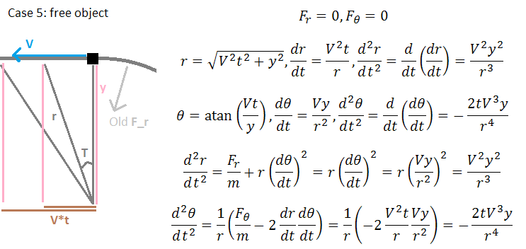
In the fifth and final case, both F_r and F_T are zero while the other quantities are free to change as necessary. This corresponds to an object that has been moving in a constant radius circle and then is suddenly released. Since there are no real forces acting on the system, we expect to fully recover the linear motion scenario (that is, a straight-line path tangent to the previously circular path of the object). Any object in this situation will have a radius of closest approach to the rotation axis, and we can analyze an object starting at this point (let this be x=0, y=const), which would therefore initially have only V_T and no V_r. In the linear frame, the object's radius will be r=sqrt(x^2+y^2), and let y=const, x=V*t where V is a linear velocity equal to V_T at t=0, then r(t)=sqrt(V^2*t^2+y^2). Similarly, T=atan(x/y) so T(t)=atan(V*t/y). Then taking the derivatives gives dr/dt=V^2*t/r(t), and dT/dt=V*y/r(t)^2. Taking second derivatives gives d^2 r/dt^2=V^2*y^2/r(t)^3, d^2 T/dt^2=-2*t*V^3*y/r(t)^4. And finally, solving the acceleration equations for the second derivatives gives d^2 r/dt^2=r(t)*(dT/dt)^2=V^2*y^2/r(t)^3, and d^2 T/dt^2=-2/r(t)*(dr/dt)*(dT/dt)=-2*V^3*t*y/r(t)^3.
The expected derivatives match those given by the formulas, therefore the system appropriately describes the free-object case. We thus conclude that these two equations are a valid representation of the rotating reference frame as viewed from an outside reference in terms of only real forces.
Now we are in a position to answer what may occur in the swing system. (See also 2022 update under Swing Acceleration which provides an important second mechanism) For the rider to accelerate, it is desirable to have d^2 T/dt^2 of the same sign as dT/dt (that is, when swinging in one direction it is desirable to swing faster in the same direction). We also know that there is no direct force F_T available to perform the acceleration. This leaves only the dr/dt term in the d^2 T/dt^2 equation available to perform acceleration, and since the sign of dT/dt has to match, we find that dr/dt must be negative. Thus angular velocity is increased when the radius of swinging is decreased! (see Coriolis force) The validity of this effect can be easily verified by swinging an object on a string in a circle while pulling in the string. This is usually explained in introductory physics classes as a side effect of 'conserving angular momentum' (which is of course given to the student without much justification), but here it is seen to arise as a direct consequence of applying Newton's laws in the rotating system.
How can the radius of swing be decreased? Assuming there is a certain center of gravity at which the rider's mass can be taken as a point, the rider can move around in the swing to bring the center of gravity closer to the swing axis, thus decreasing the radius of swing and increasing angular velocity. The angular acceleration is a product of dr/dt and dT/dt, so the mechanism is most effective during the fastest rate of swing. It should be recognized that the centrifugal force from the rider's perspective is the strongest during the fastest rate of swing, and forcing radius of swing to decrease in this interval amounts to doing work against the centrifugal force. This work is then experienced as increased angular velocity (it will be noted that work done by the rider against gravity and centripetal force is what shows up as the kinetic energy in the swing, and as long as this work exceeds the work done by gravity on the downswing, the rider will accelerate. This also explains why it is not ideal to try to do all the work at the bottom of the swing, but rather to distribute it over about 1/3 of the swing cycle centered on the bottom. As for the conservation of angular momentum - the earth gets an opposite momentum during the time that the rider is accelerating due to a moment set up by the gravitational force and the mechanical support for the swing being in different places).
A device was set up to verify this idea - in the device, an object (steel nail) swings on a string about an axis, and the string may be pulled or released to change the swing radius, but with no way to directly accelerate the object's tangential velocity. From the angular acceleration equation, we see that radial velocity can cause acceleration proportional to angular velocity. By releasing the string when the object is traveling slowly (at either end of the swing) and pulling in the string when the object is traveling quickly (at the bottom of the swing), the net angular acceleration is positive without a net change in the swing radius. Switching the timing of the actions to be opposite of the aforementioned causes the angular acceleration to be negative. In this process, if the swing amplitude increases then work is done on the swing system, and if it decreases then work is extracted. The working of the device in both accelerating and decelerating the swinging object can be seen in the attached video.
This is certainly a non-intuitive effect, and naturally the question arises how to reconcile the better-understood linear actions with the rotating reference frame. The above model does this mathematically (except for the rotation of basis vectors, all actions are taken to be linear), but a good mental image is still necessary. In my view, a better understanding may come from recognizing that forces are able to change instantaneously, while an object's momentum persists in time until an appropriate force affects it. This is already suggested in the first derivation of the centrifugal force, where the effect of the radial force, over time, is such that the object completely reverses its velocity, but instantaneously the radial force is only perpendicular to the velocity. There is no time-scale limitation to how fast a force can change or how long a momentum can last, so the time taken by an object to complete a rotation or by a force to maintain that rotation can take on any value (this is different from the notion of phase, or leading/lagging factors). In other words, while at an instant the radial force is perpendicular to the object's motion, the object nonetheless is accelerated by this force and the resulting momentum persists as it moves along the circular path. As it is further accelerated with a perpendicular force, the constantly varying forces continue to contribute to the momentum (which persists in time) to the point where later the object's motion is entirely due to such perpendicular accelerations (which have by now been replaced by forces acting perpendicular to the present line of motion, continuing the cycle). This view also can be applied successfully to understand the gyroscopic effect in 3D rotating frames.