Let's begin by going over what is meant by 'electric motor'. In a general sense, many devices can accept electrical energy to produces motion. First, we say a motor is expected to produce rotary motion - this excludes a variety of linear accelerators (railgun/coilgun, maglev train, particle accelerators). Second, the rotary motion should be easily extracted as physical movement, which excludes synchrotrons/betatrons/magnetrons. Third, a motor must not depend on a source of matter to operate, excluding various thrusters being proposed for space use. This still leaves many possibilities for what a motor can be (piezoelectric devices, thermoelectric cycle). So we impose the fifth condition that a motor should generate forces solely based on the interaction of magnetic fields. Practically the last restriction arises because generating high electric gradients is a difficult task (the repulsion between electrons makes it very difficult to store enough energy in an electric field to do work) while generating a magnetic field is relatively straightforward by simply moving electrons in a circular path. This is not to say that the other devices are not important, but rather that they have not been found to be efficient for performing everyday motion tasks.
Now we can classify motors by the way in which they cause magnetic interactions to occur. With a constant magnetic field no cyclic motion will arise spontaneously (magnetic and electric fields, like gravitational fields, are conservative so all 'free energy from magnets' attempts are similar to a perpetual motion wheel). Therefore motors need to somehow change magnetic fields over time as a result of an applied electric current. This is done by forcing the electrons to travel in loops - physically this is the loops of wire (windings) in a motor. When an electron travels in a loop, a magnetic field is created and can be used to generate forces. If a physical magnetic force is exerted on the field, the electron may either slow down or speed up, corresponding to a motor (which converts electrical energy to mechanical) or a generator (which converts mechanical energy to electrical).
The effect of a magnetic field on the rotor should be considered - the field may cause the rotor to either speed up, slow down, or remain at rest (even though electrical energy is used - this is dissipated as heat in the windings and causes a motor to burn out!). This brings us to two important concepts: Starting - is the rotor guaranteed to start turning when electrical power is applied? Direction - is the motor guaranteed to turn in a particular direction when electrical power is applied? A more formal analysis involves 'quadrants' where it is determined whether the motor can accelerate (motoring) and decelerate (generating) in a particular direction. Four quadrant operation means the motor can run forward or reverse and generate electricity when external torque is applied in either direction. This definition does not exclude motors that require energy input to function as generators, which is the case for all induction based motors.
Motors can change magnetic field as a function of the position of the rotating element (or rotor), by using carbon brushes that switch the direction in which electrical current flows while the motor is rotating. This is nice, because as long as electricity is applied to the motor it is guaranteed to start and rotate in a known direction. It is not great because the brushes are in contact with a moving surface and this causes them to wear down over time and fail. A better way to change the magnetic field is by switching the direction of electric current by some outside influence. The outside influence could be either a constant alternating frequency as supplied on power lines, or a special motor controller that creates a desired signal. It is sometimes said that brushless motors are difficult to control or start or keep running, but this is not the general case - induction motors can guarantee starting torque and direction of rotation without any semiconductors or fancy electronics required. Particular designs, such as brushless DC motors (BLDC) will require special motor controllers.
Brushed motors use physical electrical contacts to change the direction of the magnetic field inside the motor as it rotates. This changing magnetic field exerts a force that speeds up the rotor, and to do so it needs to interact with a stationary magnetic field that is supplied by magnets attached to the stator (part of motor that does not spin). The main distinctions between brushed motors are how the magnetic fields are generated. Generally, the rotor is inside the stator for brushed motors.
These motors have a set of permanent magnets that create a stationary field; these magnets are attached to the stator. The electric current flows through the brushes to the rotor, and creates the changing magnetic field that accelerates the rotor. The opposite setup, with permanent magnets attached to the rotor and the wire windings in the stator also works but is not generally used in brushed motors since brushes need to be on the rotor in either case. These motors can be found in most moving toys and in some battery-powered tools.
These motors have no permanent magnets, meaning there are windings in the stator that create the stationary field, and windings in the rotor that create a changing field. These are generally large (multi-horsepower) motors and are useful because having control of both magnetic fields can lead to better speed/torque characteristics as well as higher power density. These motors are used in heavy duty applications (elevators, compressors) and on car winches.
For simplicity we only consider the permanent magnet case, as this includes all hobby grade motors. In this case there are only two exposed contacts on the motor, through which electrical power can be supplied in the form of constant voltage (leading to constant velocity) or constant current (leading to constant torque). Generally DC power is applied (in 'universal motors' AC is used) and for operating from a battery or other constant voltage supply it is necessary to have a controller that will ensure the motor does not draw too much current. The method considered here is called Pulse Width Modulation (PWM) where pulses of electrical power are applied to the motor at a constant frequency (on the order of 10 kHz), and the pulse width can vary from zero (meaning no power is applied, motor is off) to 50% (half power) to a full period (power is always applied). So instead of changing a constant input voltage to a constant output voltage, we change a constant input voltage to a time-averaged output voltage where the average is over one pulse period.
Two circuits for PWM driving of DC motors are presented below. Both use a constant amplitude and frequency triangular wave as the basis of the PWM, and pass that wave through two comparators that either turn on or turn off the flow of electricity to the motor based on the control (input from potentiometer or throttle) voltage level.
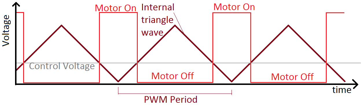
Diagram of triangle wave and output PWM pulses of the DC motor controller circuits below.
The first circuit uses two op-amps to generate the triangular wave, and two op-amps as comparators. The second circuit uses a 555 timer to generate the triangular wave, and two comparators as in the first one. On both the PWM_OUT-1 pin is meant to be connected to 'gate' terminals of many (N-channel) MOSFETs in parallel (tested with 24 parallel devices) while the PWM_OUT-2 pin is connected to the drain of the MOSFETs. Each MOSFET should have its own resistor to limit charging current. Note the arrangement of the BJTs in these circuits is opposite of the usual arrangement in this sort of circuit - this change ensures fast switching (on order of 50ns) and forces the gates to the full low or high level.
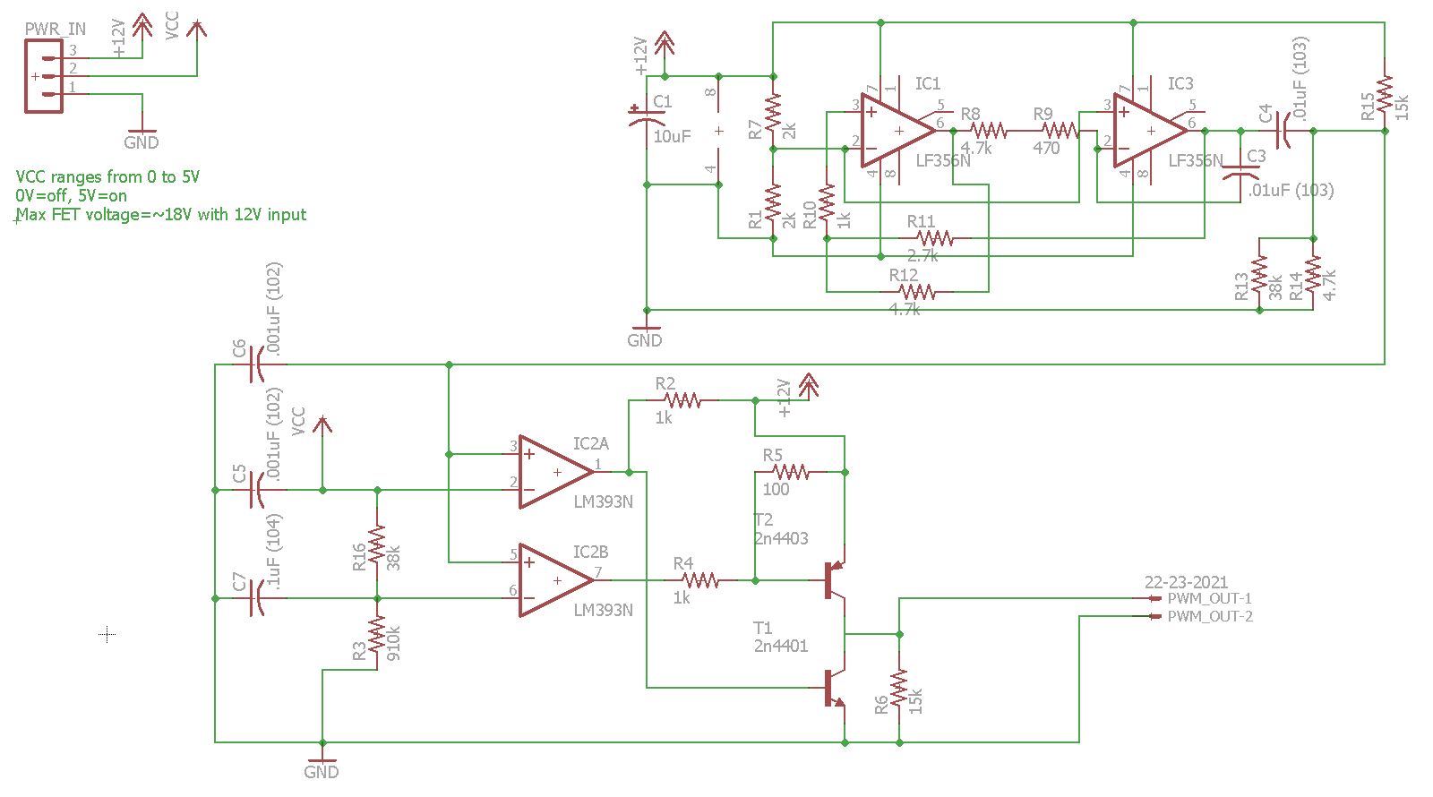
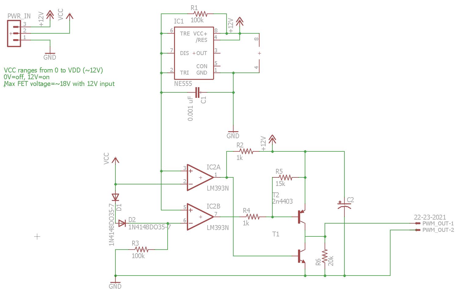
Left, schematic of the op-amp based PWM MOSFET driver (Eagle file). Right, schematic of the comparator and 555 based PWM MOSFET driver (Eagle file).
Brushless motors depend on an external influence to change the magnetic field inside the motor. Because they do not have the property of brushed motors that the magnetic field is a function of only rotor position, they are both more difficult to understand and more varied in their designs/applications. We will split them into 'controlled' and 'uncontrolled' classes, where the former requires a purpose-built controller device while the latter does not.
These motors depend on a constant time-varying electric current to generate a changing field. The most readily available varying currents are sinusoidal, and one-phase or three-phase. The frequency of these currents is a constant 60 Hz. These motors can be further divided into synchronous (rotates at 60 Hz or fraction of it) and asynchronous (lags behind the ideal synchronous speed). Note that these motors can also be used with a controller if necessary, but do not require it.
In these motors, a permanent magnet attached to the rotor interacts with a time-varying magnetic field of a constant frequency. This leads to stable operation only when the magnet is spinning exactly as fast as the external magnetic field is changing, which is synchronous operation. Synchronous motors tend to have low torque but be compact and straightforward to manufacture, in addition to guaranteeing a constant rotation speed. They are very popular as carousel spinner motors in microwaves, and have been used in clock mechanisms due to their constant speed. As they operate on a single AC phase in a microwave, there is no control over starting direction so one may note the microwave carousel rotation direction is effectively random each time the microwave is turned on.
These motors operate on the principle of induction (more widely called induction motors), and thus do not have any permanent magnets. A varying magnetic field of constant frequency is applied in such a way that electric current is induced in windings on the rotor without any brushes. The resulting current then creates another magnetic field that interacts with the stator and causes the rotor to move. This may sound like one is getting something for free - a force between two magnetic fields where one creates the other seems contradictory. What this requires is an external physical force that helps create an imbalance in one of the magnetic fields to create the electrical flow. This means that an asynchronous motor works best when there is physical resistance to motion and can never spin as fast as a synchronous motor - if it did, there would be no 'incentive' for the external magnetic field to try and repel its own counterpart. A physical analogy might be trying to get a cup to spin by stirring water inside it, where the water plays the role of an induced electric current, the stirring implement plays the role of a driving magnetic field, and the cup represents the magnetic field felt by the rotor. To cause the cup to rotate in this way requires that the stirring speed be faster than the cup's rotation speed, otherwise no forces are felt. It is not obvious what level of force will be felt by the cup as a function of stirring speed (or by the rotor as a function of electric frequency), and such questions require a detailed mathematical analysis.
Because induction plays a role in asynchronous motors, the design of the motor fully determines the direction of rotation. The design might include capacitors or inductors that effectively split one phase into two or three (shaded pole, capacitor start/run), in order to select the running direction. These motors can be easy to fabricate and find use in most desktop/household fans and microwave cooling fans. Larger induction motors are used in machine shops for lathes or mills, where typically three phase power is used directly so no circuitry is necessary to control the motor (three phases are out of phase 120 degrees from each other, which gives them a certain 'direction'. Imagine a row of lights where every other one is on, and then this pattern gets shifted to the right - it looks the same as if the original were shifted to the left. If only every third light is on, this is not the case.) Induction motors with no rotor windings (a solid metal rotor) operate based on eddy currents entirely and are used in gyroscopes for fine balancing of the rotor.
These motors will, in general, not start when given a single frequency alternating electric current, even with multiple phases. This means that an electronic controller must check the rotor position and decide what frequency and phase offset to supply to the motor. These are becoming increasingly attractive in battery-powered devices due to their compactness and reliability, because semiconductors have made small motor controllers practical. These motors can be divided by the way the magnetic fields interact.
A permanent magnet is attached to the rotor and windings in the stator create the alternatig field to cause rotation. These are also called brushless DC (BLDC) motor. This may seem very similar to the synchronous motor but an important difference exists - in general the synchronous motor operates with only one pair of magnetic poles, whereas the permanent magnet brushless motor has multiple poles which increases torque (and makes it more difficult to synchronize the rotor to the field without a controller). The motor controller requires knowledge of rotor position, which is obtained either through magnetic field sensors (which sense the magnets on the rotor) or through the stator windings (sensorless configuration - a pulse is sent through the windings and the rotor position determines how this pulse is affected, which is interpreted by the controller). Applications range from CD players and computer fans to powered bicycle wheels (hub motors) and model aircraft motors.
No permanent magnets are used, instead steel or other magnetic material is used on the rotor, which gets an induced magnetic field once an external field is applied. The rotor material is arranged in poles that are then made to line up with the stator windings. This results in the possibility of attaining power output comparable to BLDC motors using cheaper materials (steel instead of neodymium) but increased difficulty in control of the motor. The force used here is the same as what is seen when a magnet is used to pick up some steel object, like a screw or nail. The reluctance principle is used in stepper motors (along with permanent magnetic poles) in printers/scanners and similar positioning mechanisms. This motor is also used in some appliances (washing machines, hand dryers). One property of interest is that, like induction motors, when these are powered off they can spin freely (other motors suffer from some 'cogging torque' when permanent magnets move around the stator, or are slowed by friction from brushes).
Generally a controller will need to have feedback from the motor (rotor position and velocity) in order to effectively spin up the motor. This is a fairly involved task. Instead of doing that, here a few simple schematic circuits are presented that will spin small multi-phase motors (such as HDD/CD player motors) at a constant frequency. These circuits use 74LS74 D Flip-Flop ICs to generate different logic level waveforms that then drive BJTs directly. An input potentiometer R6 adjusts the frequency of the output, which determines the speed of the motor. Because there is no feedback from the motor, these circuits may not start a motor from standstill unless the frequency is set to its lowest value (using R6) and then slowly increased to the desired speed in order to maintain synchronization.
Two circuits are shown that drive small three-phase motors. Ideally the output is found by rotating a vector around the origin and representing it in 3-axis coordinates. Here instead we just alternate between the three most obvious resulting values: with (abc) representing (a) voltage for phase 1, (b) voltage for phase 2, and (c) voltage for phase 3, the output levels of the first circuit cycle through (100) (010) (001). Note that each of the phases is on for 33% of the time, and to attain this the output of phase n is given as input to the phase n+1 at the next update of the flip-flop. The second circuit instead gives the inverted output of phase n as input to phase n-1 at the next update. This results in the cycle (100) (110) (010) (011) (001) (101). Note that each of the phases is now on for 50% of the time. Compared to the first circuit this will result in a smoother rotation and easier synchronization. R4 and C1 are used to ensure a consistent starting state of (100) at power-up, and IC3 is similar in functionality to a 555 timer and is used here to generate update pulses that determine how quickly the flip-flops change their output level.
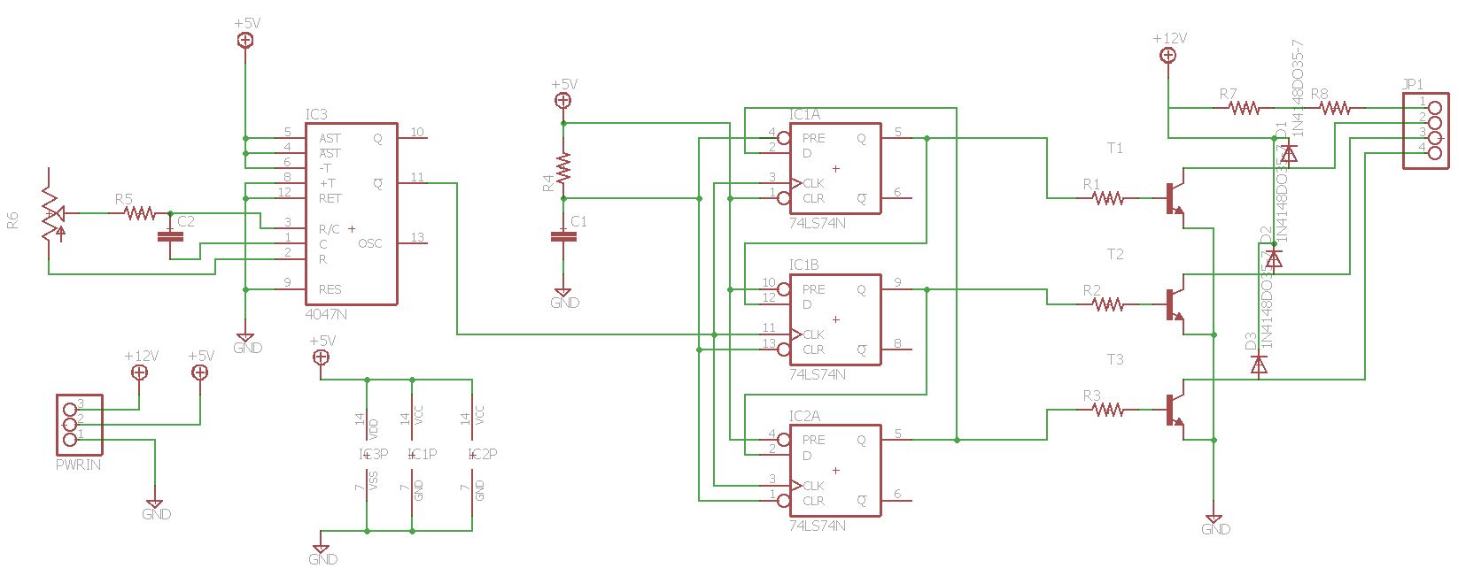
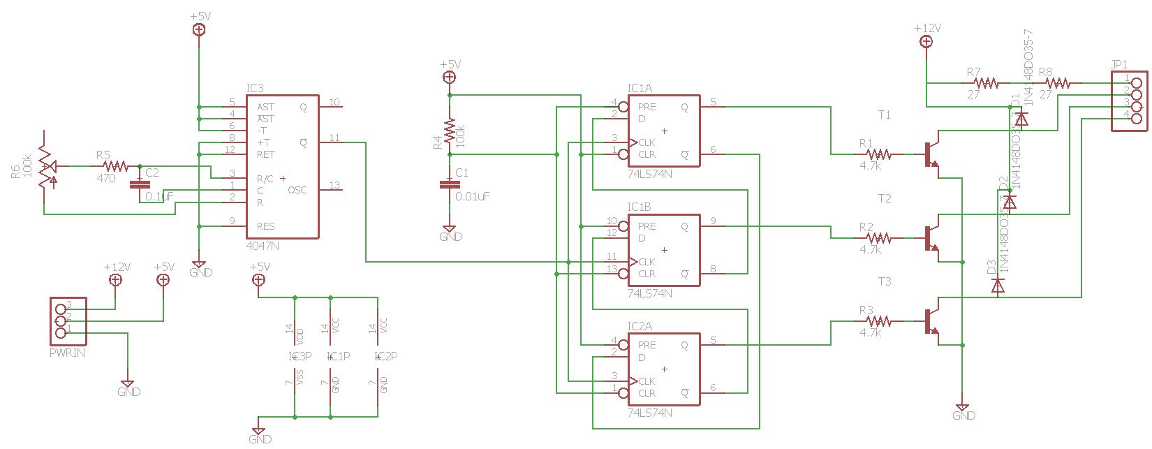
Left, the 30% phase on-time schematic for small three phase motors (Eagle file). Right, the 50% phase on-time schematic (Eagle file).
Some HDD and CD player motors are four phase. The circuit below cycles through phase voltages (1100) (0110) (0011) (1001). Whereas the three phase circuits above required three flip-flops, this four phase arrangement can be done with just two, by taking advantage of the inverted outputs. Previously we wrote the phases as (abcd) but if we write the sequence as (acbd) it will be (1010) (0110) (0101) (1001). Thus (a) and (c) are controlled by one flip-flop, and (b) and (d) are controlled by the other one. I am pretty happy with how compact this circuit is. I used it to drive the rotating mirror in the Laserscope project.
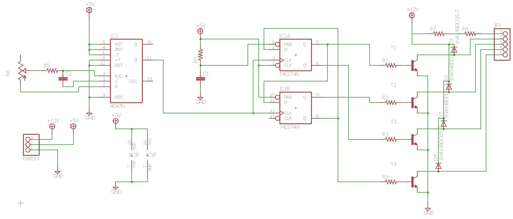
A simple two D flip-flop four phase motor driver (Eagle file).