Imagine two points, A and B, separated by some distance but at the same height (gravitational potential). If a ball is released (with zero initial velocity) at point A, in the presence of gravity it is possible to make a path between points A and B such that the ball eventually arrives at point B and then oscillates between A and B. In this scenario, different paths lead to different travel times or oscillation periods, as shown in this physics demonstration video. The ball will travel faster if it gains more kinetic energy from accelerating downwards, thus favoring a 'deep' path that allows the ball to travel downwards. However traveling downwards does not contribute to traveling from A to B (which are at the same height) so the path cannot be too 'deep'. This means there must be some fastest path between A and B, such that the ball released at A reaches B in the least amount of time by this path compared to other paths. What is this path?
It was quickly evident that my mathematics isn't quite good enough to solve this analytically. But I have a computer which can brute force the way to the solution! Such a solution doesn't necessarily prove that the fastest path is unique, but if a consistent path is found with a local optimization algorithm regardless of starting conditions then the uniqueness is a safe conclusion.
I assume that instead of a ball there is a point particle (so no angular momentum - the angular momentum will just slow down the action of gravitational acceleration and deceleration but otherwise will not affect the result, which is confirmed with the rolling balls in the above video), and simulate travel along a path as the particle having a scalar velocity magnitude which is then directed along the vector tangent to the path where the particle is located, so acting as if guided on frictionless rails. This assumption makes it possible for the particle to travel along right corners, but this isn't an issue since the particle itself doesn't have a size. The particle is accelerated along its direction of travel by the amount sin( theta ) * g / m where theta is the path's angle with the horizontal at the particle's location. This relation arises from the normal force that keeps the particle on the path counteracting the remainder of the gravitational acceleration (and the rest of the gravitational force is countered by the frictionless rail so does not need to enter the calculation). In each path increment the particle travels according to x = a * t^2 + v * t + x0 along its travel direction.
The code starts with an initial guess for a path, and then moves each point on the path up and down and tracks the local change in particle travel time. If moving one point upwards leads to a longer travel time but moving it downwards leads to a shorter travel time, the point will be moved downwards. It would be a lot of work to consider all such combinations at once, so I consider the effect of each point individually, which makes this a local optimization algorithm. The code is available here.
The numerical algorithm approaches the fastest path over 2000 iterations. The travel time is reduced from the 0.878 s for the initial guess to 0.804 s for the found solution. The calculated velocity of the particle at the end of the curve is also indicated, and remains at 0.0000 throughout the simulation reflective of the implicit energy conservation with this algorithm.
A consistent fastest path is approached regardless of the starting point, which suggests that there is indeed one fastest path. Does the resulting path have a mathematical representation? I tried a few different curves, including parabolic, catenary, semicircle. The only good match was a trochoid, the path traced by a point on a circle rolling under the straight line from A to B.
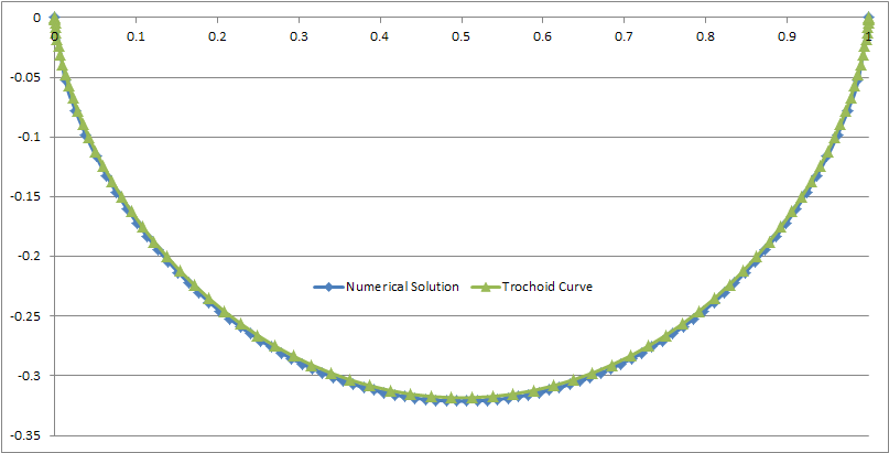
Comparison of the numerical solution and the trochoid curve.
While researching the different curves, it turns out the trochoid is indeed the analytical solution to the brachistocrone problem! An excel file with the point coordinates and the analytical formula for the trochoid curve can be downloaded here. A code to compare different paths can be downloaded here (this code does not animate the path perfectly as it uses linear interpolation for time between calculated points whereas really it should be quadratic; however on the whole the timing is correct).
Comparison of the motion of particles along different paths, with the trochoid curve finishing first.
Having the shape profile, it was tempting to 3D print a track in this shape that would allow observing the fastest path in a real experiment with a steel ball. For this it is necessary to offset the track such that the ball's center (rather than its edges) travels along the trochoid curve. To have a reference point I 3D printed a second track with a hyperbolic cosine curve, which has a similar depth and appearance. The simulation claims the ratio of travel times from A to B (cosh time / trochoid time) is only 1.027, so it will be difficult to compare but hopefully over many oscillations the trochoid will be seen to come out ahead. It turned out the plastic track was too rough and incurred friction losses so over multiple oscillations the cosh curve came out ahead (since at low oscillation amplitude the cosh has a higher frequency than the flatter trochoid). But keeping a close eye on the initial release of two balls simultaneously shows the trochoid ball consistently getting past the halfway point before the cosh ball.

The 3D printed optimal path and a similar-looking catenary curve for comparison.
The above result is a bit concerning because it implies that in a gravitational field the fastest path between two points is not a straight line. (probably this is at root due to time dilation, that is, at a higher gravitational field the elapsed time is shorter) This means that in principle, we should design our roadways using cycloidal shapes and in this way travel between points faster while using less energy. It may be impractical to build large trochoids miles long (and anyway drag and friction would prevent building up the necessary velocities at the bottom of such a long curve to achieve the desired energetic benefit), but the concept applies at all scales - so even using meter-long or 10 meter-long trochoids (which is feasible to build) should improve our transportation system in the same manner! If we consider that switching a 1 meter long section to a trochoid decreases the time from 1 s to 0.9 s, then switching a 0.1 meter section decreases the time from 0.1 s to 0.09 s, so 10 0.1 m long trochoids in series will result in the same savings, or 100 0.01 m long sections. But this doesn't seem right - there should not be the same impact at all scales, otherwise we should be nano-engineering all our road surfaces for a substantial energetic improvement and in fact nearly zero-energy transportation. The reason this doesn't work comes from the speed involved relative to distance traveled. As the initial velocity of the object increases, the time benefit of the cycloidal path relative to a straight path rapidly decreases. With an initial velocity of zero, the trochoid path was shown above to be the fastest way to get from point A to B (in this example separated by 1 meter), with a central drop of about 32 cm relative to A and B, and peak velocity at that point of about 2.5 m/s. This took 0.804 seconds, but there is not really any comparison point, because without this path the object would have remained at A indefinitely as it had zero initial velocity.
Let's compare this to the case of a car at highway speeds, say 30 m/s. Now over the same 1 meter traveled, the fastest path becomes a curve with only a 1.3 mm central drop, and peak velocity at that point of about 30.000442 m/s which is barely an improvement on the initial velocity of 30 m/s. And indeed, the time savings due to the optimized curve is only a few hundred nanoseconds, or one part in 175 thousand. Thus, meter-scale cycloidal curves won't result in any easily measurable time savings. Do smaller and larger scales work in a similar manner? On a 10 meter segment, the optimal path does not scale linearly - again the presence of the initial velocity is what breaks the linearity, because the velocity does not change relative to the length of the path. Because relative to the longer length, the time to traverse the path at the same velocity is longer, there is a greater impact that can be achieved with the trochoid. In this case of 10 m at 30 m/s, an almost 14 cm central drop, with peak speed of 30.046 m/s, achieves a time savings of 690 microseconds or 1 part in 483, which is an improvement of about 362 times on the temporal reduction that could be achieved by using 10 1 m long curves in series. Thus we cannot nano-engineer faster roads, commensurate with experience. Going up in scale to 100 m long curves, having an 11.6 m central drop and peak speed of 33.58 m/s, saves 134 ms, or 1 part in 25 (or 4%). Once again we are about 19 times better than what could be achieved with 10 10 m long curves in series. Naturally, 1 km long curves would do better still, with a 283 m central drop and peak speed of 80.3 m/s, saving 13.97 seconds or 1 part in 2.4 (or 42%), now 10 times better than 10 100 m segments. These attractive time savings however remain theoretical, because in reality drag and friction will prevent the vehicle from attaining the high speeds necessary to achieve this - at highway speeds like 30 m/s the engine is already doing a lot of work just to maintain the speed, and while gravity helps, reaching 80 m/s could only be done with essentially 100% of the accelerating energy supplied by the engine itself to counter the effects of drag, namely we could get rid of the road gradient and the load on the engine to reach these speeds will be almost unchanged. Thus we cannot save practical amounts of energy with trochoids and high speed transportation.
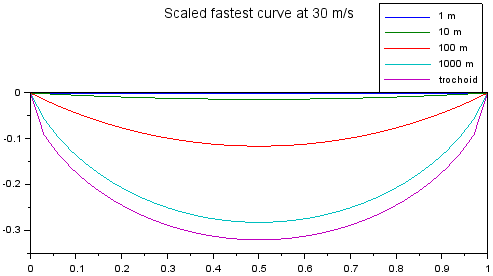
The fastest paths between two equal-height points, plotted on scaled axes with an initial velocity of 30 m/s. It can be seen that as the length scale increases, and the time to travel between the points in a straight line becomes longer, the fastest path becomes increasingly trochoid-like, while at shorter distances the path is increasingly straight. The curves in between the trochoid and the line are not proportional to the trochoid and were calculated numerically (file available here).
The picture changes when we consider a leisurely bike ride. With an initial velocity of 3 m/s, on a 10 m section, we could have a 2.8 m central drop, leading to a peak speed of 7.99 m/s and a time reduction of 42% compared to a flat 10 m path. It seems that with 1/10 of velocity, the result is similar to what we saw above for 100x distance, so the scaling is v^2/d. While the time savings is real, such a path would look more akin to a skate park than to a regular bike path, which is probably why we don't see this in use - though this could definitely be put to use by designers of ski resorts, roller coasters, skate parks I guess, and similar attractions. As before, if we go to longer 100 m sections, the peak speeds become so high that losses prevent easy recovery of the energy on the uphill side, while if we go to shorter 1 m sections, the time savings reduce to only 4% - which is still something to consider, especially for racing sports where such margins matter (for example, potentially using a rocking motion in wind surfing to force a curved path along the z axis in the water along the waves, or picking slightly bumpier terrain when skiing).