The first classes on electricity and circuits typically cover three components: resistors, capacitors, and inductors. These form the basis for more advanced circuits, because it is seen that even wires can have resistive, capacitive, and inductive properties. However these properties are not very intuitive and difficult to observe directly. In this article I outline two physical analogs of the basic electrical circuit, one based on flowing water and one based on rotating shafts. Both analogs satisfy the same equations as their electrical counterparts, while providing some intuition on how the circuit functions.
This is the standard model used to describe electrical circuits. There are two variables - voltage and current - denoted V and I, and experiments show that these two are sufficient to describe what happens when a wire carries electricity (describing the underlying electric and magnetic fields). There are also two ways to arrange components - series and parallel - because each of the three passive components has two connection points/leads. When components are connected in series (end to end) each sees the same current but only a fraction of the overall voltage, and when they are connected in parallel (alongside) each sees the same voltage but only a fraction of the overall current.
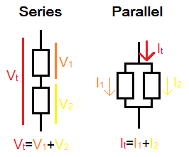
Two components connected in series and in parallel. In series, the voltage across each component is summed to give the overall voltage across both components, and current through both is equal. In parallel, the current through each component is summed to give the overall current through both components, and voltage across both is equal.
A way of mathematically codifying this notion of series and parallel is Kirchoff's laws, which 'conserve' the current and voltage throughout a circuit. This is ensured by the concise requirement that at any junction (where multiple leads are connected) the voltages are equal on all leads and the currents flowing into the junction along all leads must sum to zero.
Once components are connected in series or parallel, they can be seen as a 'combined component' with just two connection points/leads, and can be connected to other components following the same rules; the concept of series/parallel is thus sufficient to describe complicated circuits. Resistance, capacitance, and inductance can be combined in two ways: sum (A=B+C) and inverse sum (1/A=1/B+1/C). Both resistors and inductors are conventionally defined in terms of voltage: V=R*I and V=L*dI/dt, while capacitors are defined in terms of current: I=C*dV/dt which can be re-written as V=(1/C)*int(I*dt) showing the voltage proportional to 1/C. Thus, because of the definition of capacitance, when the resistors and inductors follow the sum rule, capacitors follow the inverse sum rule (and vice versa).
Resistors connected in series behave like a single resistor, with the overall resistance being a sum of individual resistances. Same for inductors and inductances. Capacitors in series act as a single capacitor, but as pointed out above the overall capacitance is an inverse sum of individual capacitances.
Resistors connected in parallel behave like a single resistor, with the overall resistance being an inverse sum of individual resistances. Same for inductors and inductances, and using the non-inverse sum for capacitors and capacitances.
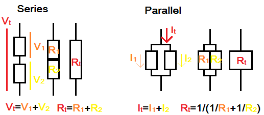
An illustration of resistors in series and in parallel. In series, they can be drawn together as a 'long resistor' which has a higher resistivity due to a longer path for electron flow; in parallel they can be drawn as a 'wide resistor' which has a lower resistivity due to a greater area for electrons to flow through.
One might imagine that electrons flowing in a wire are similar to water molecules flowing in a pipe. The logical analogy, to maintain the concepts of series and parallel, is to use mass flow rate m (mass of water flowing through a given tube per unit time) as analogous to current, and to use water pressure P as analogous to voltage. If two parallel pipes are used instead of one, the mass flow rate (current) through each is a fraction of the total. If two pipes are connected in series, the pressure drop (voltage) across each one is a fraction of the total.
We can then simply use pipes as a resistor analog, and say P=R*m where R combines pipe properties like length and roughness. A higher R means it takes more pressure to drive the same amount of water (per unit time) through the pipe compared to a lower R pipe.
What will the capacitors look like in this model? To match the electrical model, we simply substitute m, P wherever I, V appear in the original formulas. So, here the capacitor must follow P=(1/C)*int(m*dt) or that the pressure is an integral of mass flow rate. This can be represented by a rubber diaphragm accumulator whose volume is proportional to C.
Inductors in this model have to follow P=L*dm/dt or that the pressure depends on the rate of change of mass flow rate (or acceleration). This can be represented by a particularly long or spiral/helical pipe, which requires acceleration of a large volume of water to establish a given flow rate. A fast change in the mass flow rate, such as by closing a valve at the end of the long pipe, leads to a large pressure proportional to L. This effect can be used to pump water, as in the hydraulic ram, and is directly analogous to the boost converter.
From this model we may intuit that all wires act as resistors and inductors, and that longer wires will have higher resistance and inductance (which all happens to be correct). The water hammer effect happens to match the inductive spike (as in a spark plug) which can generate high voltages.
In this mechanical analog, the rotation of a shaft represent the flow of electricity along a wire. Rotation is used instead of linear motion because then a DC system does not 'fly apart'. Components in series will transmit the same force (torque), while components in parallel will experience the same speed at either end. So, we replace I, V with F, v representing force (torque) and velocity (angular velocity).
A resistor in this model is represented as a fluid coupling (or 'rotational dashpot'/viscous damper). It follows v=R*F or that achieving a certain velocity requires a higher force in case of larger R. The velocity in this model is not absolute - it is measured between the two ends of the fluid coupling.
A capacitor in this model follows v=(1/C)*int(F*dt), which can be re-written as F=C*dv/dt=C*a. This is Newton's F=m*a with C=m. It is tempting to interpret a capacitor as simply a moving or rotating mass, but this does not give the 'two terminals' necessary to connect capacitors in series or in parallel. Instead a model might be something like a planetary gearbox connected to a 'momentum wheel'. The wheel spins at the relative speed between the two inputs to the gearbox. These units can be connected in series and the resulting speed of each wheel will be a fraction of the input speed while torque will be transmitted throughout, as desired.
An inductor in this model follows v=I*dF/dt or F=(1/L)*int(v*dt)=(1/L)*x. The latter is Hooke's F=k*x with (1/L)=k. Thus a (torsional) spring is an appropriate analogue.
Connecting the spring to a mass (inductor to capacitor) intuitively shows that an oscillating system can be established. The linear version of this mechanical system is commonly used to explain inductor-capacitor circuits. The rotational version as described here can also handle DC voltages and series-to-parallel changes (such as buck or boost converter) with realistic components.
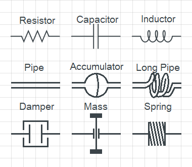
A symbolic comparison of the electrical (current-voltage), water (mass flow rate-pressure), and shaft (torque-velocity) models.
The above models were chosen because they not only match the equations defining the three passive components, but also transfer mechanical energy in the same way as the electrical system. The pressure drop in a pipe and viscous friction in a fluid coupling both dissipate energy similar to the resistor. Diaphragm accumulators and rotating masses store energy similar to the capacitor, and long pipes and springs store energy similar to the inductor.
But all I have really done is replace I, V with other variables and the resulting equations happened to describe potentially practical devices. Instead of claiming that inductors are like springs, it's possible to say that resistors are like springs since V=R*I is quite like F=k*x, which we might rewrite as x=(1/k)*F to keep a consistent notion of series/parallel (since force is the analog to current as discussed above). So it is possible to represent a resistor circuit as a collection of springs, and vice versa. This analogy can be used to quickly analyze mechanical spring systems using knowledge from electrical circuits. But, using this mapping means that capacitors are represented as dampers (F=C*dx/dt=C*v) and inductors as unusual devices that increase the force as a function of time spent at a point. The overall scheme still conserves energy, but does not correspond to conventional notions of energy transfer or to easily constructed devices. Nonetheless for single-component systems, such as resistor/spring/thermal conductor/pipe networks, such analogies can simplify analysis by applying a common framework.