I came across a series of videos (YouTube channel HowNot2) regarding the topic of setting up a highline - typically a long (hundreds of meters) stretch of flat webbing stretched between two cliff edges, so that it is possible to walk across the line from one cliff to the other. In one approach, a thin and light "tag line", such as fishing line, is strung between the two anchor points, and then this is used to pull increasingly thicker and heavier ropes until there is sufficient rope strength to pull the webbing. An issue when doing this is that the weight of the rope pulls downwards, and if the tension in the line is not controlled while pulling the rope across the drop, a heavier rope may simply fall down to the ground instead of being pulled towards the other anchor point. It appears that an optimal configuration exists with minimum rope tension, because the tension is based on both angle of the rope at the anchor points and the total mass of hanging rope. In this article I explain the properties of this configuration and implications for practical rigging.
It is an established result that the weight of a free-hanging rope with a constant weight per unit length is described by a catenary curve. The function y=cosh(x) represents this shape for any situation of two support points when translated and scaled to travel through the two points (one degree of freedom represents the rope tension). If the two supports are not at the same elevation (y-coordinate), the curve is a cropped fragment of a symmetric curve which would travel to a virtual support that is at the same elevation as the topmost support. Because of this symmetry with regard to the minimum elevation of the rope, I describe the problem in terms of Horizontal Distance from an anchor to the rope's lowest point, and vertical Droop from the elevation of the anchor to the elevation of the rope's lowest point. For the case of same-elevation anchors, the Horizontal Distance is always half of the straight-line distance between the anchors; otherwise the Horizontal Distance becomes longer when viewed from the top anchor.
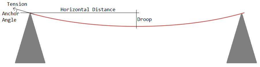
2D drawing describing the parameters used in the calculation. A red rope is stretched between two anchor points. For the analysis, we define Horizontal Distance, Droop, Anchor Angle, and Tension.
Given a constant Horizontal Distance, it is possible to vary the Droop, then easily fit a cosh(x) function through the anchor and the minimum point. The rope length is equal to the arc length of the catenary curve, and the hanging weight of the rope is the rope length multiplied by the rope weight per length. The rope tension is then determined by a statics diagram at the anchor: it is such that the rope hanging weight is supported at the angle of the rope through the anchor. Note that as defined here the horizontal distance and the rope hanging weight represent only half of the rope in the symmetrically supported case, however the tension is still correct because the full rope (with twice the weight) has two anchors pulling up on it.
For practical scenarios, droop will not be larger than the horizontal distance, because otherwise the rope angle at the anchor approaches -90 deg and this is not useful for walking the highline. Maximum acceptable tension limits the minimum droop, because for zero droop the required tension approaches infinity. In the following, I plot the region of droop between 0.1 x and 1 x the horizontal distance. The Scilab code for this calculation can be downloaded here.
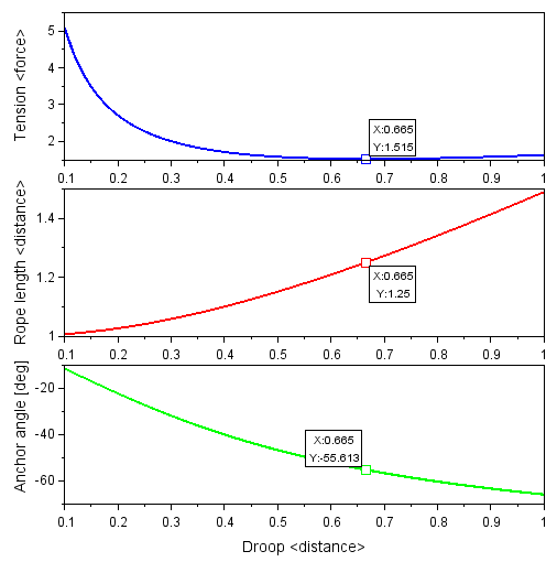
Plots of Tension, Rope Length, and Anchor Angle as a function of Droop. The minimum-tension point is marked on all three plots with a datatip. <distance> is scaled to Horizontal Distance, while <force> is scaled to the weight of a rope whose length is the Horizontal Distance.
As suspected, there is a point of minimum tension that occurs when droop is 0.665 x horizontal distance, and this minimum tension is 1.515 x the weight of the rope whose length is the horizontal distance. At this point the hanging rope length is 1.25 x the horizontal distance, and the anchor angle is -55.6 deg. This minimum is due to the interplay between tension and weight: when the rope is pulled towards a straight line, this requires more tension but decreases the amount of hanging weight, and when the rope is allowed to hang down in a U shape, this requires less tension but increases the amount of hanging weight. The minimum tension point is not very strong, that is, the tension increases slowly on either side, and the rate of increase is effectively constant for increasing droop while it becomes steeper for decreasing droop. To make use of this curve for a rope between two anchors of nearly equal elevation:
When pulling a heavier rope by a lighter rope, the weight will first be concentrated more at one anchor and later will be balanced at the other. The limiting case will be that of the heavier rope covering the entire span, so the tension values expected then can be used to set up the rigging. At the anchor where the rope is released, there must be a device that limits the rate of release while maintaining tension (otherwise the rope will simply fall into the gap). The minimum acceptable tension at which the device must stop the rope (minimum of static or dynamic friction) should be 1.515 x the force scaling defined above (add more to account for wind forces). If the stopping force is lower than this, the rope will be subject to runaway release under its own weight. If the stopping force is much higher than this, the process of pulling the rope across the gap will require more effort and generate more heat than necessary. With a properly operating rope release, there is no reason to have more rope than 1.25 x the horizontal distance.
Drawing a horizontal line in the tension plot at the minimum stopping force for a tension-based release device, two intersection points result - one towards the left of the plot where the tension is primarily due to pulling the rope tight, and one towards the right of the plot where the tension is primarily due to the rope's hanging weight. Between these intersection points, the tension in the rope is insufficient to release more rope, while outside these points, the tension in the rope causes additional release. On the left side of the plot, rope release is stable because extra rope causes a decrease in tension with more slack. On the right side of the plot, rope release is unstable because extra rope causes an increase in tension with more weight. The rope release system should ensure a sufficient stability margin with its stopping force, but due to the slow change of tension versus droop, this would practically necessitate a setpoint of some 2 x to 3 x force scaling. To minimize effort without sacrificing stability, the change in anchor angle should be used, because the anchor angle monotonically decreases with rope release. Therefore, instead of a tension-based rope release, consider using an angle-based release, where the force exerted by the device depends on the angle at which the rope exits the anchor. Set for the minimum force to occur at an angle of -55.6 deg, and for the force to increase at more negative (steeper) angles at a rate higher than the limiting slope on the right of the tension plot. The force may decrease at more positive (flatter) angles because the rope release is stable in this region. Then pulling at the minimum tension will automatically be achieved by controlling the rope angle at one anchor. This approach is easier to dial in compared to a tension based release, because placing the stop condition anywhere from -51.2 deg to -59.7 deg will achieve a release force no higher than 1.01 x the calculated minimum, independent of rope weight. An example mechanism for angle-controlled release is shown below. This approach can also be implemented with pulleys and more conventional gear.
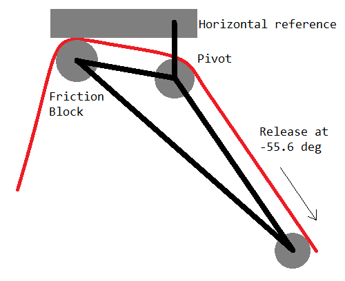
A possible angle-controlled friction release mechanism that will minimize tension when pulling a rope across a gap. The rope is pulled from across the gap at the right. When the angle of the rope becomes too steep, the rope pushes down on the bottom roller, which rotates the mechanism about the pivot and increases the friction at the friction block, so the release stops. When the angle of the rope is less steep, there is reduced force on the bottom roller, the friction decreases, and more rope is released.
Another outdoor trick is to drop objects from a cliff to estimate the cliff height using the time delay between dropping the object and hearing the sound of the object hitting the ground. This is described by a quadratic equation which includes the acceleration due to gravity (9.8 [m*s^-2]) and the speed of sound (343 [m*s^-1]). A few solutions of this equation are listed in the table below for reference.
| Sound after drop [s] | Object fall time [s] | Height of drop [m] |
|---|---|---|
| 0.5 | 0.496 | 1.207 |
| 1 | 0.986 | 4.764 |
| 1.5 | 1.469 | 10.57 |
| 2 | 1.945 | 18.55 |
| 2.5 | 2.416 | 28.61 |
| 3 | 2.881 | 40.68 |
| 3.5 | 3.340 | 54.68 |
| 4 | 3.794 | 70.54 |
| 4.5 | 4.242 | 88.20 |
| 5 | 4.686 | 107.6 |
| 5.5 | 5.124 | 128.6 |
| 6 | 5.558 | 151.4 |
| 6.5 | 5.987 | 175.6 |
| 7 | 6.412 | 201.4 |
| 7.5 | 6.833 | 228.7 |
| 8 | 7.249 | 257.5 |
| 8.5 | 7.661 | 287.6 |
| 9 | 8.069 | 319.0 |
| 9.5 | 8.474 | 351.8 |
| 10 | 8.874 | 385.9 |